カテゴリ
- 学童・教育用品(29)
さらに商品を絞り込む
ブランド
ARTESYN EMBEDDED TECHNOLOGIES・SPARKFUN・RS PRO・SKF(日本エスケイエフ)・DUCATI・MICROCHIP・三菱ふそう・HAMMOND・AMPHENOL・HARLEY-DAVIDSON・ブランドをもっと見る
- ARTESYN EMBEDDED TECHNOLOGIES(40)
- SPARKFUN
- RS PRO(20)
- SKF(日本エスケイエフ)(10)
- DUCATI(9)
- MICROCHIP(8)
- 三菱ふそう(6)
- HAMMOND(6)
- AMPHENOL(5)
- HARLEY-DAVIDSON(5)
- ブランドをもっと見る
商品レビュー
レビューで絞り込む
価格
価格で絞り込む
出荷目安
当日・翌日以内・翌々日以内・3日以内・4日以内
「mbed」の検索結果
特価
 SparkFun MicroMod RP2040 ProcessorSPARKFUN
¥4,398税込¥4,838
1個
33日以内出荷
Description<br />The SparkFun MicroMod Pi RP2040 Processor Board is a low-cost, high-performance board with flexible digital interfaces featuring the Raspberry Pi Foundation's RP2040 microcontroller. With the MicroMod M.2 connector, connecting your MicroMod Pi RP2040 Processor Board is a breeze. Simply match up the key on your processor's beveled edge connector to the key on the M.2 connector and secure it with a screw(included with all Carrier Boards).<br />The RP2040 utilizes dual ARM Cortex-M0+ processors(up to 133MHz):264kB of embedded SRAM in six banks<br />6 dedicated IO for SPI Flash(supporting XIP)<br />30 multifunction GPIO:Dedicated hardware for commonly used peripherals<br />Programmable IO for extended peripheral support<br />Four 12-bit ADC channels with internal temperature sensor(up to 0.5 MSa/s)<br />USB 1.1 Host/Device functionality<br />The RP2040 is supported with both C/C++ and MicroPython cross-platform development environments, including easy access to runtime debugging. It has UF2 boot and floating-point routines baked into the chip. The built-in USB can act as both device and host. It has two symmetric cores and high internal bandwidth, making it useful for signal processing and video. While the chip has a large amount of internal RAM, the board includes an additional external flash chip.<br />MicroMod is a modular interface ecosystem that connects a microcontroller "processor board" to various "carrier board" peripherals. Utilizing the M.2 standard, the MicroMod standard is designed to easily swap out processors on the fly. Pair a specialized carrier board for the project you need with your choice of compatible processor!<br />Get Started with the MicroMod RP2040 Processor Guide<br />Features<br />RP2040 General Features<br />Dual Cortex M0+ processors, up to 133 MHz<br />264 kB of embedded SRAM in 6 banks<br />6 dedicated IO for QSPI flash, supporting execute in place(XIP)<br />30 programmable IO for extended peripheral support<br />SWD interface<br />Timer with 4 alarms<br />Real time counter(RTC)<br />USB 1.1 Host/Device functionality<br />Supported programming languages<br />MicroPython<br />C/C++<br />Specific Peripherals made available on MicroMod RP2040<br />1x USB dedicated for programming and debug(Host capable)<br />2x UARTs<br />2x I2C<br />2x SPI<br />29x GPIO<br />2x Digital Pins<br />3x Analog Pins<br />16x PWM<br />128Mbit/16MB(external)flash memory<br />Status LED<br />VIN Level ADC
アズワン品番67-0423-49
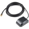
 GPS/GNSS Magnetic Mount Antenna - 3m SMASPARKFUN
¥4,498税込¥4,948
1個
33日以内出荷
Description<br />Normal GPS antennas are optimized for the US based GPS reception which is great but with more and more modules capable of tracking additional constellations(termed GNSS receivers)you're going to need the right antenna! This exceptional GPS/GNSS antenna is designed for both GPS and GLONASS reception. When used in conjunction with the SparkFun GPS ground plate this antenna achieved excellent TTFF and SIV statistics for both GPS and GLONASS constellations. The magnetic mount allows it to be easily mounted to a metal base such as a ground plate or car roof. The antenna is terminated with a 3m cable and standard SMA connector.<br />We recommend this antenna for RTK use when combined with the ground plate. If you need Beidou reception and additional gain consider the GPS/GNSS embedded antenna.<br />Features<br />Dimensions:50x38x17mm<br />Weight:75g including 3m cable<br />Frequency Range:1575 - 1610MHz<br />GPS Center Frequency:1575.42MHz<br />GLONASS Center Frequency:1602MHz<br />LNA Voltage:3 to 5VDC<br />LNA Gain:28dB<br />LNA Current:10mA<br />Termination Connector:SMA<br />Impedance:50Ω<br />Right hand polarization<br />Cable Length:3 meter
アズワン品番67-0423-72
 PureThermal Mini Pro JST-SR with FLIR Lepton 3.5SPARKFUN
¥119,800税込¥131,780
1個
33日以内出荷
Description<br />The new PureThermal Mini Pro JST-SR with Thermal by FLIR is a hackable thermal camera for the FLIR Lepton thermal imaging camera core. Just like its PureThermal 2 predecessor, it ships pre-configured to operate as a plug-and-play UVC 1.0 USB thermal webcam that will work with standard webcam and video apps on all major platforms using a JST-SR to USB Cable, or your own custom cable. For developers, its reference firmware and viewer software are open source.<br />It has multiple connection options such as solder straight to the board or a custom cable using the JST-SR port. The PTMini Pro also features four mounting holes, less complex circuitry, and perhaps best of all, USB DFU. This is a development kit ready to be embedded into a production system.<br />Each board comes with a FLIR Lepton 3.5.<br />The FLIR Lepton(R)is a radiometric-capable LWIR camera solution that is smaller than a dime, fits inside a smartphone, and is one tenth the cost of traditional IR cameras. Using focal plane arrays of either 160x120 or 80x60 active pixels, Lepton easily integrates into native mobile-devices and other electronics as an IR sensor or thermal imager. The radiometric Lepton captures accurate, calibrated, and noncontact temperature data in every pixel of each image.<br />Features<br />PureThermal:Compatible with all production FLIR Leptons, including radiometric 2.5 and 3.5 cores<br />9 Hz color video over usb using the USB UVC class<br />STM32F412 ARM microprocessor - execute on-board image processing without need for an external system<br />Open source reference firmware:GroupGets PureThermal Github<br />Works with GetThermal - our custom open source thermal video display software for macOS and Linux with radiometric support<br />DFU over USB using a JST-SR port to USB cable, or a modified USB cable and the through holes.<br />Four mounting holes<br />Compact form-factor ready to be embedded into production systems<br />FLIR Lepton 3.5:Thermal sensitivity:< 50 mK(0.050℃)<br />Spectral Range:8 - 14 microns(nominal)Long Wave Infrared(LWIR)<br />Resolution:160h×120v pixels<br />Radiometric Accuracy - High Gain Mode:Greater of +/- 5℃ or 5%(typical); Low Gain Mode:Greater of +/- 10℃ or 10%(typical)<br />Scene Dynamic Range - High Gain Mode:-10° to +140℃; Low Gain Mode:-10° to +400℃(at room temperature), -10° to +450℃(typical)<br />Pixel Size:12 micrometers<br />Frame Rate:8.7 Hz(effective)<br />Output Format:User-selectable 14-bit, 8-bit(AGC applied), or 24-bit RGB(AGC and colorization applied)<br />Horizontal Field of View(HFOV):57°<br />Lens Type:f/1.1<br />Size(w×l×h):10.50×12.70×7.14 mm<br />Weight:0.9 grams<br />Power Consumption:150 mW typical, 650 mW during shutter event, 5mW standby<br />Optimum Operating Temperature Range:-10℃ to + 80℃
アズワン品番67-0423-44
 SparkFun Thing Plus - RP2040SPARKFUN
¥6,698税込¥7,368
1個
33日以内出荷
Description<br />The SparkFun Thing Plus - RP2040 is a low-cost, high performance board with flexible digital interfaces featuring the Raspberry Pi Foundation's RP2040 microcontroller. Besides the Thing Plus or<br />Feather<br />footprint(with 18 GPIO pins), the board also includes an SD card slot, 16MB(128Mbit)flash memory, a JST single cell battery connector(with a charging circuit and fuel gauge sensor), an addressable WS2812 RGB LED, JTAG PTH pins, four(4-40 screw)mounting holes, and our signature Qwiic connector.<br />The RP2040 contains two ARM Cortex-M0+ processors(up to 133MHz)and features:264kB of embedded SRAM in six banks<br />6 dedicated IO for SPI Flash(supporting XIP)<br />30 multifunction GPIO:Dedicated hardware for commonly used peripherals<br />Programmable IO for extended peripheral support<br />Four 12-bit ADC channels with internal temperature sensor(up to 0.5 MSa/s)<br />USB 1.1 Host/Device functionality<br />The RP2040 is supported with both C/C++ and MicroPython cross-platform development environments, including easy access to runtime debugging. It has UF2 boot and floating-point routines baked into the chip. While the chip has a large amount of internal RAM, the board includes an additional 16MB of external QSPI flash memory to store program code.<br />The SparkFun Qwiic Connect System is an ecosystem of I2C sensors, actuators, shields and cables that make prototyping faster and less prone to error. All Qwiic-enabled boards use a common 1mm pitch, 4-pin JST connector. This reduces the amount of required PCB space, and polarized connections mean you can't hook it up wrong.<br />Get Started With the Thing Plus RP2040 Hookup Guide<br />Features<br />SparkFun Thing Plus - RP2040 Features<br />Raspberry Pi Foundation's RP2040 microcontroller<br />16MB QSPI Flash Memory<br />JTAG PTH Pins<br />Thing Plus(or Feather)Form-Factor:18[1]x Multifunctional GPIO Pins[2]<br />Four available 12-bit ADC channels with internal temperature sensor(500kSa/s)<br />Up to eight 2-channel PWM<br />Up to two UARTs<br />Up to two I2C buses<br />Up to two SPI buses<br />USB-C Connector:USB 1.1 Host/Device functionality<br />2-pin JST Connector for a LiPo Battery<br />(not included)<br />500mA charging circuit<br />Qwiic Connector<br />Buttons:Boot<br />Reset<br />LEDs:PWR<br />- Red 3.3V power indicator<br />CHG<br />- Yellow battery charging indicator<br />25<br />- Blue status/test LED(<br />GPIO 25<br />)<br />WS2812<br />- Addressable RGB LED(<br />GPIO 08<br />)<br />Four Mounting Holes:4-40 screw compatible<br />Dimensions:2.3"×0.9"<br />RP2040 General Features<br />Dual Cortex M0+ processors, up to 133 MHz<br />264 kB of embedded SRAM in 6 banks<br />6 dedicated IO for QSPI flash, supporting execute in place(XIP)<br />30 programmable IO for extended peripheral support<br />SWD interface<br />Timer with 4 alarms<br />Real time counter(RTC)<br />USB 1.1 Host/Device functionality<br />Supported programming languages<br />MicroPython<br />C/C++<br />1.<br />Note:<br />GPIO 08<br />is not included in this count, as it passes through the WS2812 addressable RGB LED first.<br />GPIO 07<br />and<br />GPIO 23<br />are counted as a single GPIO because they are tied together.<br />2.<br />Note:The GPIO pins are programmable so you can reconfigure the pins! Check out the RP2040 datasheet for more information on the GPIO functionality.
アズワン品番67-0423-56
 SparkFun Cryptographic Co-Processor Breakout - ATECC608A QwiicSPARKFUN
¥1,198税込¥1,318
1個
33日以内出荷
<br />Description<br />Product Restrictions:To access certain features of the ATECC608A, users will need to contact Microchip and sign an NDA contract to obtain the complete datasheet. Due to the required NDA - technical support, an Arduino library, and hookup guide are not provided for users on this product.<br />The SparkFun ATECC608A Cryptographic Co-processor Breakout allows you to add strong security to your IoT node, edge device, or embedded system. This includes<br />a<br />symmetric<br />authentication,<br />symmetric<br />AES-128 encryption/decryption, and much more. As stated above, the ATECC608A has limited Arduino support and the complete datasheet is under NDA with Microchip.<br />This breakout board includes two Qwiic ports for plug and play functionality. Utilizing our handy Qwiic system, no soldering is required to connect it to the rest of your system. However, we still have broken out 0.1"-spaced pins in case you prefer to use a breadboard. The ATECC608A chip is capable of many cryptographic processes, including, but not limited to:Creating and securely storing unique asymmetric key pairs based on Elliptic Curve Cryptography(FIPS186-3).<br />AES-128:Encrypt/Decrypt, Galois Field Multiply for GCM<br />Creating and verifying 64-byte digital signatures(from 32-bytes of message data).<br />Creating a shared secret key on a public channel via Elliptic Curve Diffie-Hellman Algorithm.<br />SHA-256 HMAC Hash including off-chip context save/restore<br />Internal high quality FIPS random number generator.<br />Embedded in the chip is a 10Kb EEPROM array that can be used for storing keys, certificates, data, consumption logging, and security configurations. Access to the sections of memory can then be restricted and the configuration locked to prevent changes. Each ATECC608A Breakout ships with a guaranteed unique 72-bit serial number and includes several security features to prevent physical attacks on the device itself, or logical attacks on the data transmitted between the device.<br />A summary datasheet for the ATECC608A is available here. The full datasheet is under NDA with Microchip. You will need to contact them for access to the entire datasheet. Meanwhile, the ArduinoATECCX08 Library currently only supports the ATECC608A with SAMD21 Arduino boards.<br />We do have much more support for the ATECC508A version of this chip. Please check out our ATECC508A Hookup Guide and Arduino Library(which includes six examples). This will get you familiar with the basics of elliptic curve cryptography and signing/verifying data with the ATECC508A version of the chip.<br />Note:The I2C address of the ATECC608A is 0x60 and is software-configurable to any address. A multiplexer/Mux is required to communicate to multiple ATECC608A sensors at the default address when on a single bus. If you need to use more than one ATECC608A sensor at the default address, consider using the Qwiic Mux Breakout.<br />Note:The ATECC608A can be only configured once before it is<br />PERMANENTLY<br />locked<br />. It is advisable that users purchase multiple boards in order to use other configurations and explore the advanced functions of the ATECC608A.<br />Additionally, this board<br />IS<br />capable of encrypting and decrypting data. However, to access these additional features, you will need to contact Microchip and sign an NDA contract to obtain the complete datasheet.<br />It is recommended that an SparkFun RedBoard Turbo - SAMD21 Development Board is used with this product due to the buffer size required on the I2C bus.<br />The SparkFun Qwiic Connect System is an ecosystem of I2C sensors, actuators, shields and cables that make prototyping faster and less prone to error. All Qwiic-enabled boards use a common 1mm pitch, 4-pin JST connector. This reduces the amount of required PCB space, and polarized connections mean you can't hook it up wrong.<br /><br />Features<br />Operating Voltage:2.0V-5.5V(<br />Default on Qwiic System:3.3V<br />)<br />Active Current Draw(for ATECC608A):16 mA<br />Sleep Current(for ATECC608A):<150 nA<br />Guaranteed Unique 72-bit Serial Number<br />10 Kb EEPROM Memory for Keys, Certificates, and Data<br />Storage for up to 16 Keys<br />256-bit Key Length<br />Internal High-Quality FIPS Random Number Generator(RNG)<br />Configurable I2C Address(7-bit):0x60(<br />Default<br />)
アズワン品番67-0423-59
 SparkFun Beefy 3 - FTDI Basic BreakoutSPARKFUN
¥4,998税込¥5,498
1個
33日以内出荷
<br />Description<br />This is SparkFun Beefy 3 FTDI Basic Breakout for the FTDI FT231X USB to serial IC. The pinout of this board matches the FTDI cable to work with official Arduino and cloned 3.3V Arduino boards. It can also be used for general serial applications. Built upon the same foundation as our 3.3V SparkFun FTDI Basic Breakout, the Beefy 3 is equipped with an AP2112K voltage regulator making this FTDI basic breakout board capable of handling a current load of up to 600 mA! With the addition of a more "Beefy" voltage regulator your will now be able to power a 3.3V project directly from the FTDI. The pinout of this board matches the FTDI cable to work with official Arduino and cloned 3.3V Arduino boards.<br />This board brings out the DTR pin as opposed to the RTS pin of the FTDI cable. The DTR pin allows an Arduino target to auto-reset when a new Sketch is downloaded. This is a really nice feature to have and allows a sketch to be downloaded without having to hit the reset button. This board will auto reset any Arduino board that has the reset pin brought out to a 6-pin connector. The pins labeled BLK and GRN correspond to the colored wires on the FTDI cable. The black wire on the FTDI cable is GND, green is DTR. Use these BLK and GRN pins to align the FTDI basic board with your Arduino target.<br />There are pros and cons to the FTDI Cable vs the FTDI Basic. This board has TX and RX LEDs that allow you to actually see serial traffic on the LEDs to verify if the board is working, however this board now requires a Micro-B USB cable. The FTDI Cable is well protected against the elements, but is large and cannot be embedded into a project as easily. The FTDI Basic uses DTR to cause a hardware reset where the FTDI cable uses the RTS signal.<br />This board was designed to decrease the cost of Arduino development and increase ease of use(the auto-reset feature rocks!). Our Arduino Pro and LilyPad boards use this type of connector.
アズワン品番67-0430-06
 SparkFun Inventor's Kit for Arduino Uno - v4.1SPARKFUN
¥28,980税込¥31,878
1個
33日以内出荷
<br />Description<br />The SparkFun Inventor's Kit(SIK)for Arduino Uno is a great way to get started with programming and hardware interaction with the Arduino programming language. The SIK includes everything you need to complete five overarching projects consisting of 16 interconnected circuits that teach everything from blinking an LED to reading sensors. The culminating project is your very own autonomous robot! No previous programming or electronics experience is required to use this kit.<br />The online guide contains step-by-step instructions with circuit diagrams and hookup tables for building each project and circuit with the included parts. Full example code is provided, new concepts and components are explained at point of use, and troubleshooting tips offer assistance if something goes wrong.<br />The kit does not require any soldering and is recommended for beginners ages 10 and up who are looking for an Arduino starter kit. For SIK version 4.1 we took an entirely different approach to teaching embedded electronics. In previous versions of the SIK, each circuit focused on introducing a new piece of technology. With SIK v4.1, components are introduced in the context of the circuit you are building, and each circuit builds upon the last, leading up to a project that incorporates all of the components and concepts introduced throughout the guide. With new parts and a completely new strategy, even if you've used the SIK before, you're in for a brand-new experience!<br />This version of the SIK replaces the SparkFun RedBoard Qwiic with the Arduino Uno(SMD version)and comes without the SIK guidebook and carrying case. With these components being swapped and removed, we were able to reduce the overall size and weight of the kit, making shipping cheaper and easier for anyone ordering internationally.<br />Note:As stated above, this SIK does NOT include a carrying case or print guidebook.<br />Get Started With the SparkFun Inventor's Kit v4.1 Experiment Guide<br />Examples<br />Project 1:Light<br />Circuit 1A:Blinking an LED<br />Circuit 1B:Potentiometer<br />Circuit 1C:Photoresistor<br />Circuit 1D:RGB Night-Light<br />Project 2:Sound<br />Circuit 2A:Buzzer<br />Circuit 2B:Digital Trumpet<br />Circuit 2C:"Simon Says" Game<br />Project 3:Motion<br />Circuit 3A:Servo Motors<br />Circuit 3B:Distance Sensor<br />Circuit 3C:Motion Alarm<br />Project 4:Display<br />Circuit 4A:LCD "Hello, World!"<br />Circuit 4B:Temperature Sensor<br />Circuit 4C:"DIY Who Am I?" Game<br />Project 5:Robot<br />Circuit 5A:Motor Basics<br />Circuit 5B:Remote-Controlled Robot<br />Circuit 5C:Autonomous Robot
アズワン品番67-0424-34
 SparkFun USB Thumb Drive 16GBSPARKFUN
¥3,698税込¥4,068
1個
33日以内出荷
Description<br />With the cost of microSD cards on a consistent rise, it's always useful to have an economical and reliable option as a backup for storing your files. This sleek, red 16GB thumb drive has been emblazoned with our SparkFun Electronics logo a
アズワン品番67-0428-08
 SparkFun Wireless Joystick KitSPARKFUN
¥12,980税込¥14,278
1個
33日以内出荷
<br />Description<br />The SparkFun Wireless Joystick Kit provides an easy way to control your next XBee project. Before the wireless joystick, radio-controlled projects used hobby RC transmitters, the same ones used for RC cars, boats and planes. The problem with these transmitters is that many aren't customizable, and the ones that are tend to be too expensive for many of us. The Wireless Joystick Kit offers a custom wireless solution for those who want to control their project their own way.<br />Equipped with the increasingly popular SAMD21 onboard, all you need is to assemble the SparkFun Wireless Joystick into the configuration you want and add your own XBee and lithium ion battery into the provided sockets. The Wireless Joystick Kit can be assembled into a configuration that utilizes dual joysticks for better RC steering robots(like tanks)or a single joystick configuration with four 12mm momentary pushbuttons(a setup similar to what older game consoles used). We have provided a full Hookup Guide that gives assembly instructions, as well as a tank-steering motor controller tutorial to help get you started!<br />Please be aware that the SparkFun Wireless Joystick Kit is<br />NOT supported on Windows 7/8<br />due to a lack of support drivers for those specific OS's.<br />Note:This kit will need to be assembled before use, so a beginner's knowledge of soldering will be required. Additionally, in an effort to keep shipping rates down and make this kit available to people throughout the world without delay, there is no XBee or lithium ion battery included.<br />Get Started with the Wireless Joystick Kit Guide
アズワン品番67-0424-08
 Poke Home Connector - 2-PinSPARKFUN
¥129税込¥142
1個
33日以内出荷
Description<br />Poke Home Connectors have been featured on a number of our boards over the last few years by providing a simple screw-terminal-type connector for easy wire connection purposes. Similar to screw terminals, Poke Home Connectors grasp a wire entered into the receiving area of the pin-out by pressing down on the small plastic strip at the end of the housing. Doing so raises the internal clamp and, upon release of the button secures the wire in place without any soldering required.<br />Poke Home Connectors work better in environments with a lot of vibrations(i.e. automotive applications)or when a wire is expanding or contracting due to temperature cycling. Additionally, the tension in the connector is automatically adjusted to the wire gauge(assuming it is within the accepted wire thickness)as opposed to variances in tension when a user tightens the screw terminal.
アズワン品番67-0425-83
 Raspberry Pi - GPIO Shrouded Header 2x13SPARKFUN
¥219税込¥241
1個
33日以内出荷
Description<br />This 2x13 shrouded header has the same number and spacing of pins as the Raspberry Pi so you can easily connect via ribbon cable to the low-level peripherals and get hacking! This through-hole header has 26 0.1"-spaced pins and is keyed for
アズワン品番67-0430-16
 microSD Card - 1GB Class 4SPARKFUN
¥1,998税込¥2,198
1個
33日以内出荷
Description<br />For the times when all you need is a basic SD card this is the card for you. 1GB capacity is plenty to store MP3s or log environmental data, and still dwarfs older memory systems like magnetic core memory.<br />This card is not the Ferrari of SD technology, but that's what makes it perfect to use in permanent projects that require non-volatile storage. It is a Class 4 SDHC card with rated transfer speeds up to 4 MB/s. A simple test on our PC showed the available space as 942 MB and a write speed of ~5 MB/s.<br />No adapter is included because you probably have them coming out of your ears at this point.<br />Features<br />SDHC format<br />1GB capacity<br />Class 4(4MB/s)
アズワン品番67-0421-34
 Raspberry Pi Compute Module 3+ LiteSPARKFUN
¥9,398税込¥10,338
1個
33日以内出荷
Description<br />The Raspberry Pi Compute Module 3+ Lite contains the guts of a Raspberry Pi 3 Model B+(the BCM2837 processor and 1GB LPDDR2 RAM). This module allows a designer to leverage the Raspberry Pi hardware and software stack in their own custom systems and form factors. In addition this module has extra IO interfaces over and above what is available on the Raspberry Pi model A/B boards, opening up more options for the designer.<br />This is all integrated onto a small(67.6mm×31mm)board that fits into a standard DDR2 SODIMM connector. You get the full flexibility of the BCM2837 SoC(which means that many more GPIOs and interfaces are available than with a standard Raspberry Pi), and designing the Module into a custom system should be relatively straightforward because all the tricky bits have been put onto the Module itself.<br />The CM3+ Lite product is the same as CM3+ except the eMMC Flash is not fitted, and the SD/eMMC interface pins are available for the user to connect their own SD/eMMC device. Note that the CM3+ is electrically identical and, with the exception of higher CPU z-height, physically identical to the legacy CM3 products.<br />Note:The CM3+ modules require a software/firmware image dated November 2018 or newer to function correctly.<br />Features<br />Broadcom BCM2837B0, Cortex-A53(ARMv8)64-bit SoC @ 1.2GHz<br />1GB LPDDR2 SDRAM<br />Operating Supply Voltage:1.8V, 3.3V<br />Minimum Operating Temperature:-25C<br />Maximum Operating Temperature:+80C<br />HDMI, MIPI, USB, and GPIO interfaces on edge connector
アズワン品番67-0423-17
 Header - 2x5 Pin Male, 1.27mmSPARKFUN
¥609税込¥670
1個
33日以内出荷
Description<br />This is a super small, 2x5 pin male PTH header. This header is in the common configuration for JTAG applications. Each pin has a spacing of 1.27mm in between each other and can be cut down to smaller increments if the need arises.<br />Features<br />Pin style:square<br />Number of pins:10(2x5)<br />Pin spacing:1.27mm(0.05")
アズワン品番67-0425-69
 LIDAR-Lite v3HPSPARKFUN
¥37,980税込¥41,778
1個
33日以内出荷
Description<br />LIDAR has never looked so good! This is the LIDAR-Lite v3HP, a compact, high-performance optical distance measurement sensor from Garmin(TM). The LIDAR-Lite v3HP is<br />the<br />ideal optical ranging solution for drone, robot, or unmanned vehicle applications. Each sensor is housed in a durable, IPX7-rated housing and includes all the core features and user configurability of the popular LIDAR-Lite v3.<br />The v3HP is very similar in function to that of the v3 but it can now sample faster at rates greater than 1kHz(where as the v3 is only capable of up to 500Hz). Another improvement is that this v3HP model is more power efficient with current consumption rates 40mA less than the v3(that's 65mA as opposed to 105mA while idle, and 85mA instead of 130mA while acquiring).<br />Each LIDAR-Lite v3HP has a range of 1m to 40m and features an edge-emitting, 905nm(1.3 watts), single-stripe laser transmitter, 8m Radian beam divergence, and an optical aperture of 12.5mm. This version of the LIDAR-Lite still operates at 5VDC(6V max)with a peak power of 1.3W and still possesses an accuracy of +/- 2.5cm at >2m. On top of everything else, the LIDAR-Lite is user-configurable, allowing adjustment between accuracy, operating range and measurement time and can be interfaced via I2C or PWM with the attached 200mm cable.<br />Note:CLASS 1 LASER PRODUCT CLASSIFIED EN/IEC 60825-1 2014. This product is in conformity with performance standards for laser products under 21 CFR 1040, except with respect to those characteristics authorized by Variance Number FDA-2016-V-2943 effective September 27, 2016.<br />Get Started with the LIDAR-Lite v3HP Guide<br />Features<br />Resolution:1 cm<br />Typical accuracy:+/- 2.5cm at distances greater than 2 meters(Refer to operating manual for complete operating specifications)<br />Range:1m to 40m<br />Update rate:Greater than 1kHz<br />Interface:I2C or PWM<br />Power(operating voltage):4.75-5VDC; 6V Max<br />Current consumption:65ma idle; 85ma during acquisition<br />Operating temperature:-20℃ to 60℃<br />Laser wave length/Peak power:905nm/1.3W<br />Beam divergence:8m Radian<br />Optical aperture:12.5mm<br />Water rating:IPX7<br />Unit dimensions:24.5mm×53.5mm×33.5mm(1.0in×2.1in×1.3in)<br />Weight:34g(1.2oz)
アズワン品番67-0426-76
 SparkFun MicroMod Artemis ProcessorSPARKFUN
¥5,598税込¥6,158
1個
33日以内出荷
Description<br />Leveraging the ultra powerful Artemis Module, the SparkFun MicroMod Artemis Processor is the brain board of your dreams. With a Cortex-M4F with BLE 5.0 running up to 96MHz and with as low power as 6uA per MHz(less than 5mW), the M.2 MicroMod connector allows you to plug in a MicroMod Carrier Board with any number of peripherals. Let's have a look at what this processor board has to offer! If you need Machine Learning capabilities, Bluetooth, I2C functionality to connect to all our amazing Qwiic boards, and more the Artemis Processor is the perfect choice for your MicroMod Carrier Board.<br />At the heart of SparkFun's Artemis Module is Ambiq Micro's Apollo3 processor, whose ultra-efficient ARM Cortex-M4F processor is spec'd to run TensorFlow Lite using only 6uA/MHz. We've routed two I2C buses, eight GPIO, dedicated digital, analog, and PWM pins, multiple SPI as well as QuadSPI, and Bluetooth to boot. You really can't go wrong with this processor. Grab one today, pick up a compatible carrier board, and get hacking!<br />MicroMod is a modular interface ecosystem that connects a microcontroller "processor board" to various "carrier board" peripherals. Utilizing the M.2 standard, the MicroMod standard is designed to easily swap out processors on the fly. Pair a specialized carrier board for the project you need with your choice of compatible processor!<br />Get Started with the MicroMod Artemis Processor Guide<br />Features<br />Artemis General Features<br />1M Flash / 384k RAM<br />48MHz / 96MHz turbo available<br />6uA/MHz(operates less than 5mW at full operation)<br />48 GPIO - all interrupt capable<br />31 PWM channels<br />Built in BLE radio and antenna<br />10 ADC channels with 14-bit precision with up to 2.67 million samples per second effective continuous, multi-slot sampling rate<br />2 channel differential ADC<br />2 UARTs<br />6 I2C buses<br />6 SPI buses<br />2/4/8-bit SPI bus<br />PDM interface<br />I2S Interface<br />Secure 'Smart Card' interface<br />FCC/IC/CE Certified(ID Number 2ASW8-ART3MIS)<br />Specific Peripherals made available on MicroMod Artemis:1x USB dedicated for programming and debug<br />1x UART with flow control<br />2x I2C<br />1x SPI<br />1x Quad-SPI<br />8x Fast GPIO<br />2x Digital Pins<br />2x Analog Pins<br />2x PWM<br />1x Differential ADC pair<br />Status LED<br />VIN Level ADC<br />Additional peripherals are available but are shared on dedicated MicroMod pins.
アズワン品番67-0423-05
 Day of the Geek - Soldering Badge Kit WhiteSPARKFUN
¥2,498税込¥2,748
1個
33日以内出荷
Description<br />The Day of the Dead only comes around once year but what if you could celebrate it any day you want? With this white version of the Day of the Geek soldering kit you will be able to learn the basics of soldering by being able to assemble light-up skull badge! Each Day of the Geek kit takes about 5-10min to assemble with basic soldering materials(not included). Say no to sugar skulls and say yes to solder skulls instead!<br />Every Day of the Geek Soldering Badge Kit includes one white skull PCB, CR2032 battery holder, pin back, and three pairs of colored LEDs so you have the option of Red, White or Blue eyes. All you need to supply(besides soldering iron and solder)is CR2032 coin cell battery since it is<br />not<br />included to make shipping easier. Due to the different forward voltages and current draw, you shouldn't mix the LED colors. Only use red with red, white with white, and blue with blue.<br />Happy Dia de los Muertos, everyone!<br />Note:Since this product is kit, assembly and basic knowledge of soldering will be required. The Day of the Geek Badge does not come pre-assembled.
アズワン品番67-0424-17
 Sweepy 2.0 69mmSPARKFUN
¥20,980税込¥23,078
1個
33日以内出荷
Description<br />Sweepy 2.0 is our new Dust Boot made from clear polycarbonate.<br />Version 2.0 features a number of enhancements, that stem from customer feedback. These include:Sweepy 65 V2 - now can now travel up and down the spindle body allowing greater flexibility when milling<br />Now fits a 2.5" Shopvac as standard<br />Includes adapters for:2.5" direct hose<br />2.25" shop vac<br />36mm Festool/Fein<br />Includes our affectionally-named "Winston" a clear brush free base for 3d carving and video making<br />This 69mm size is for the Dewalt spindles.<br />Sweepy mounts directly to your spindle and is clamped with a machined quick-release. The compact design means that no travel is lost, and it works with any Shapeoko Z-axis with no adapters. The lower half is detachable and held in place using neodymium magnets, which means that the top half remains in place while the lower half detaches for easy access when changing bits.<br />(For the legal sticklers out there, the Shapeoko and Compact Router shown in the photos are not included with Sweepy.)
アズワン品番67-0429-12
 heART - Surface Mount Soldering KitSPARKFUN
¥5,598税込¥6,158
1個
33日以内出荷
Description<br />Be still my beating heart! With the heART Surface Mount Soldering Kit you will be able to learn the basics of SMD soldering by being able to assemble a beating heart pendant! Each heART kit takes about 20-40min to assemble depending on your soldering skill level with basic soldering materials(not included). This little kit provides a great learning tool to help you practice and improve your overall soldering skills without proving to be an impossible challenge!<br />Every heART pendant kit includes one heart-shaped PCB, a CR2032 SMD battery holder, SMD LEDs, capacitors, switch, and an ATtiny85(the heart of the heART). All you need to supply(besides a soldering iron and solder)is a CR2032 coin cell battery since it is<br />not<br />included to make shipping easier and some way to hang the completed pendant from your neck when you assemble it. The battery you provide should last over a week if left on continuously and much longer if switched off when not in use.<br />Note:Since this product is a kit, assembly and a healthy knowledge of soldering will be required. The heART pendant kit does not come pre-assembled.
アズワン品番67-0424-20
 SparkFun Qwiic Alphanumeric Display - COMシリーズSPARKFUN
¥2,298税込¥2,528
1個
33日以内出荷
Description<br />The SparkFun Alphanumeric Display Arduino library makes printing strings to the display as easy as calling the print()function. With this library, you'll be able to send I2C commands to the VK16K33 LED driver chip to light up segments(including the decimal point or colon)and even scroll your string across the display. You can download the library through the Arduino library manager by searching 'SparkFun Alphanumeric Display' or you can get the GitHub repo as a .zip file and install the library from there.<br />The SparkFun Qwiic Connect System is an ecosystem of I2C sensors, actuators, shields and cables that make prototyping faster and less prone to error. All Qwiic-enabled boards use a common 1mm pitch, 4-pin JST connector. This reduces the amount of required PCB space, and polarized connections mean you can't hook it up wrong.<br />Get Started with the Qwiic Alphanumeric Display Hookup Guide<br />Features<br />Operating Voltage:3.3V<br />Integrated RC oscillator<br />Maximum display segment numbers:128 patterns<br />13×3 matrix key scan circuit<br />16-step dimming circuit<br />I2C Addresses:0x70(0x71, 0x72, 0x73)<br />2x Qwiic connectors<br />2x Wall Mounting Points
アズワン品番67-0421-61
 SparkFun Beefcake Relay Control Kit Ver. 2.0SPARKFUN
¥2,898税込¥3,188
1個
33日以内出荷
Description<br />Your 5V system can wield great power with this big, beefy relay board. How does 10A on the NC contacts and 20A on the NO contacts at 220VAC sound? The SparkFun Beefcake Relay Control Kit contains all the parts you need to get your high-power load under control. Only minimal assembly is required!<br />The heart of the board is sealed, SPDT 20A/10A Relay. The relay is controlled by 5V logic through transistor, and an LED tells you when the relay is closed. This is kit, so it comes as through-hole parts with assembly required, which makes for some nice soldering practice. Screw terminal connectors on either side of the board make it easy to incorporate into your project.<br />There are some pretty beefy traces connecting the relay to the load pins, but the 3-pin terminals are only rated for 15A max! If you plan on connecting larger load, you'll need to solder directly to the board. As always with high current and voltage, play it safe and use your judgment when deciding how much of load you want to put on board -- in open airflow the PCB can handle the full 20A for few minutes at time, but in an enclosed area heat can build up.<br />Note:Please keep in mind that this board is really meant for someone with experience and good knowledge of electricity. If you're uncomfortable soldering or dealing with high voltage, please check out the IoT Power Relay. The IoT Power Relay is fully enclosed, making it lot safer.<br />Get Started With the Beefcake Hookup Assembly Guide<br />Features<br />Voltage Rating:220VAC/28VDC<br />VCC requirements:4-6V, 150mA capable<br />SPDT pins exposed(Form C)<br />14 AWG screw terminals for relay connections.<br />10 AWG solder lugs for relay connections.<br />Flyback diode included<br />Zener recovery diode included(decreases turn-off time)<br />Heavy oz. copper on PCB
アズワン品番67-0424-03
 SparkFun Qwiic Alphanumeric Display - COMシリーズSPARKFUN
¥2,298税込¥2,528
1個
33日以内出荷
Description<br />The SparkFun Alphanumeric Display Arduino library makes printing strings to the display as easy as calling the print()function. With this library, you'll be able to send I2C commands to the VK16K33 LED driver chip to light up segments(including the decimal point or colon)and even scroll your string across the display. You can download the library through the Arduino library manager by searching 'SparkFun Alphanumeric Display' or you can get the GitHub repo as a .zip file and install the library from there.<br />The SparkFun Qwiic Connect System is an ecosystem of I2C sensors, actuators, shields and cables that make prototyping faster and less prone to error. All Qwiic-enabled boards use a common 1mm pitch, 4-pin JST connector. This reduces the amount of required PCB space, and polarized connections mean you can't hook it up wrong.<br />Get Started with the Qwiic Alphanumeric Display Hookup Guide<br />Features<br />Operating Voltage:3.3V<br />Integrated RC oscillator<br />Maximum display segment numbers:128 patterns<br />13×3 matrix key scan circuit<br />16-step dimming circuit<br />I2C Addresses:0x70(0x71, 0x72, 0x73)<br />2x Qwiic connectors<br />2x Wall Mounting Points
アズワン品番67-0421-62
 SparkFun Qwiic Alphanumeric Display - COMシリーズSPARKFUN
¥2,398税込¥2,638
1個
33日以内出荷
Description<br />The SparkFun Alphanumeric Display Arduino library makes printing strings to the display as easy as calling the print()function. With this library, you'll be able to send I2C commands to the VK16K33 LED driver chip to light up segments(including the decimal point or colon)and even scroll your string across the display. You can download the library through the Arduino library manager by searching 'SparkFun Alphanumeric Display' or you can get the GitHub repo as a .zip file and install the library from there.<br />The SparkFun Qwiic Connect System is an ecosystem of I2C sensors, actuators, shields and cables that make prototyping faster and less prone to error. All Qwiic-enabled boards use a common 1mm pitch, 4-pin JST connector. This reduces the amount of required PCB space, and polarized connections mean you can't hook it up wrong.<br />Get Started with the Qwiic Alphanumeric Display Hookup Guide<br />Features<br />Operating Voltage:3.3V<br />Integrated RC oscillator<br />Maximum display segment numbers:128 patterns<br />13×3 matrix key scan circuit<br />16-step dimming circuit<br />I2C Addresses:0x70(0x71, 0x72, 0x73)<br />2x Qwiic connectors<br />2x Wall Mounting Points
アズワン品番67-0421-64
 SparkFun Qwiic Alphanumeric Display - COMシリーズSPARKFUN
¥2,298税込¥2,528
1個
33日以内出荷
Description<br />The SparkFun Alphanumeric Display Arduino library makes printing strings to the display as easy as calling the print()function. With this library, you'll be able to send I2C commands to the VK16K33 LED driver chip to light up segments(including the decimal point or colon)and even scroll your string across the display. You can download the library through the Arduino library manager by searching 'SparkFun Alphanumeric Display' or you can get the GitHub repo as a .zip file and install the library from there.<br />The SparkFun Qwiic Connect System is an ecosystem of I2C sensors, actuators, shields and cables that make prototyping faster and less prone to error. All Qwiic-enabled boards use a common 1mm pitch, 4-pin JST connector. This reduces the amount of required PCB space, and polarized connections mean you can't hook it up wrong.<br />Get Started with the Qwiic Alphanumeric Display Hookup Guide<br />Features<br />Operating Voltage:3.3V<br />Integrated RC oscillator<br />Maximum display segment numbers:128 patterns<br />13×3 matrix key scan circuit<br />16-step dimming circuit<br />I2C Addresses:0x70(0x71, 0x72, 0x73)<br />2x Qwiic connectors<br />2x Wall Mounting Points
アズワン品番67-0421-63
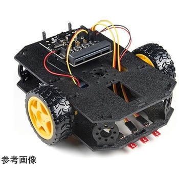 SparkFun micro:bot kit for micro:bit - v2.0SPARKFUN
¥22,980税込¥25,278
1個
33日以内出荷
Description<br />Robots are fun, and the micro:bit is the perfect controller for learning how to build and program robots! Combining the micro:bit with the SparkFun moto:bit carrier board creates a flexible, low-cost, Qwiic-enabled robotics platform for robot enthusiasts young and old! With the SparkFun micro:bot kit you will be able to create simple robots quickly without spending hours learning how to build and program your bot.<br />Inside each micro:bot kit you will find all the components required to build your micro:bit into a robotics powerhouse; the only part that's not included is the micro:bit itself. Simply add your own micro:bit to the provided moto:bit, assemble the kit, and you will be ready to start moving. The SparkFun micro:bot kit is a great way to get your feet wet in the world of robotics.<br />The kit does not require any soldering and is recommended for anyone curious about robotics or the micro:bit platform.<br />Note:The SparkFun micro:bot kit does<br />NOT<br />include a micro:bit board. The micro:bit board will need to be purchased separately.<br />The micro:bit is a pocket-sized computer that lets you get creative with digital technology. Between the micro:bit and our shield-like bit boards you can do almost anything while coding, customizing and controlling your micro:bit from almost anywhere! You can use your micro:bit for all sorts of unique creations, from robots to musical instruments and more. At half the size of a credit card, this versatile board has vast potential!<br />Get started with the micro:bot kit Guide
アズワン品番67-0424-41
 SparkFun ProtoShield KitSPARKFUN
¥4,498税込¥4,948
1個
33日以内出荷
Description<br />The SparkFun ProtoShield Kit lets you customize your own Arduino shield using whatever circuit you can come up with and then test it to make sure everything is working the way it should! The SparkFun ProtoShield Kit is based off the Arduino R3's footprint that allows you to easily incorporate it with favorite Arduino-based device.<br />One of our favorite features with this version of the ProtoShield Kit is the solderable-like breadboard prototyping area! Half of this area was designed with a breadboard in mind. On the underside of the shield you will be able to see open jumper pads between each through hole to make a connection like a breadboard. Once you add a component, simply add a solder jumper between holes to make a connection. For those that prefer the standard prototyping pads, we left the other side(near the BlueSMiRF and Serial UART ports)as is.<br />We have also moved the prototype testing components(those used to make sure your circuit works effectively)off of the "mainland" of the shield and onto a ProtoSnap styled, removable PCB. On this test area you will find soldering areas for the two yellow 3mm LEDs(as well as pins to control and power them), two 330 Ohm resistors, a 10K Ohm resistor, and a pushbutton.<br />Note:<br />Since this product is a kit, assembly and a basic knowledge of soldering will be required. The SparkFun ProtoShield Kit does not come pre-assembled.<br />Get Started With the SparkFun ProtoShield Kit Guide<br />Features<br />Arduino R3 Footprint<br />Soldering Kit<br />Solderable-Like Breadboard<br />BlueSMiRF or Comparable 6-pin Pins<br />Detachable Test Area
アズワン品番67-0422-25
 SparkFun micro:climate kit for micro:bit - v3.0SPARKFUN
¥33,980税込¥37,378
1個
33日以内出荷
Description<br />The SparkFun micro:climate kit is a full weather station kit that is built on top of the weather:bit carrier board. Unlike previous weather kits we've carried, this micro:climate kit is Qwiic enabled and includes our tried-and-true Weather Meters and Soil Moisture Sensor, so whether you're an agriculturalist, a professional meteorologist or a hobbyist, you will be able to build a high-grade weather station powered by the micro:bit. You can even talk via wireless communication between two micro:bits with this kit to be able to monitor the weather without being exposed to it!<br />Inside each micro:climate kit you will find all the components required to build your micro:bit into a go-to weather sensor; the only parts not included are two AAA batteries, microSD card, and the micro:bit itself. Simply add your own micro:bit to the provided weather:bit, assemble the kit, and you will be ready to start sensing. The SparkFun micro:climate kit is a great way to get your feet wet in high-grade sensors --- just not literally; that's the weather:bit's job!<br />The kit does not require any soldering and is recommended for anyone curious about weather-sensing technology or the micro:bit platform.<br />The micro:bit is a pocket-sized computer that lets you get creative with digital technology. Between the micro:bit and our shield-like bit boards you can do almost anything while coding, customizing and controlling your micro:bit from almost anywhere! You can use your micro:bit for all sorts of unique creations, from robots to musical instruments and more. At half the size of a credit card, this versatile board has vast potential!<br />Note:The SparkFun micro:climate kit does<br />NOT<br />include a micro:bit board. The micro:bit board will need to be purchased separately. You will also need a microSD card when logging data and AAA batteries to power remotely.<br />Get started with the micro:climate kit Guide
アズワン品番67-0424-40
 One-Wire Ambient Temperature Sensor - MAX31820SPARKFUN
¥1,498税込¥1,648
1個
33日以内出荷
<br />Description<br />The MAX31820 ambient temperature sensor provides 9-bit to 12-bit Celsius temperature measurements with ±0.5℃ accuracy over a +10℃ to +45℃ temperature range. Over its entire -55℃ to +125℃ operating range, the device has ±2.0℃ accuracy.<br />The device communicates over a one-wire bus that, by definition, requires only one data line(and ground)for communication with a central microprocessor. In addition, the device can derive power directly from the data line, eliminating the need for an external power supply. Requiring so few pins enables the device to be placed in a 3-pin TO-92 package. The form factor of this package allows the device to be placed above the board and thus measure the ambient temperature of a system, as opposed to the board temperature that a surface-mount package would measure.<br />Each MAX31820 has a unique 64-bit serial code, which allows multiple MAX31820 devices to function on the same one-wire bus. Therefore, it is simple to use one microprocessor to control many devices distributed over a large area.<br />Features<br />Unique one-wire interface requires only one port pin for communication<br />Each device has a unique 64-bit serial code stored in onboard ROM<br />Multidrop capability simplifies distributed temperature-sensing applications<br />Requires no external components<br />Can be powered from data line; 3.0V to 3.7V power-supply range<br />Measures temperatures from -55℃ to +125℃<br />±0.5℃ accuracy from +10℃ to +45℃<br />Thermometer resolution is user-selectable from 9 bits to 12 bits<br />Converts temperature to 12-bit digital word in 750ms(Max)<br />User-definable nonvolatile(NV)alarm settings<br />Alarm search command identifies and addresses devices whose temperature is outside programmed limits(Temperature Alarm Condition)<br />Available in 3-pin TO-92 package<br />TO-92 package allows measurement of ambient temperature<br />Software compatible with the DS1822 and DS18B20
アズワン品番67-0426-62
 SparkFun Qwiic Alphanumeric Display - WhiteSPARKFUN
¥2,298税込¥2,528
1個
33日以内出荷
Description<br />We are quite familiar with seven-segment displays. We see them on our alarm clocks, ovens, and microwaves. By adding more segments to each digit you can display more than just numbers! Introducing the brand new SparkFun Qwiic Alphanumeric Display. These white fourteen-segment digits allow you display all sorts of numbers, characters, and symbols. With Qwiic, simply plug it in and go. No soldering, no figuring out which is SDA or SCL, and no voltage regulation or translation required!<br />The SparkFun Alphanumeric Display Arduino library makes printing strings to the display as easy as calling the print()function. With this library, you'll be able to send I2C commands to the VK16K33 LED driver chip to light up segments(including the decimal point or colon)and even scroll your string across the display. You can download the library through the Arduino library manager by searching 'SparkFun Alphanumeric Display' or you can get the GitHub repo as a .zip file and install the library from there.<br />The VK16K33 also supports I2C address configuration. Simply close a combination of the address jumpers on the back and you can communicate with up to four displays on the same bus. Our slim board design also features detachable stand off holes, vertical Qwiic connectors, and internal mounting holes.<br />The SparkFun Qwiic Connect System is an ecosystem of I2C sensors, actuators, shields and cables that make prototyping faster and less prone to error. All Qwiic-enabled boards use a common 1mm pitch, 4-pin JST connector. This reduces the amount of required PCB space, and polarized connections mean you can't hook it up wrong.<br />Get Started with the Qwiic Alphanumeric Display Hookup Guide<br />Features<br />White display<br />Operating Voltage:3.3V<br />Integrated RC oscillator<br />Maximum display segment numbers:128 patterns<br />13×3 matrix key scan circuit<br />16-step dimming circuit<br />I2C Addresses:0x70(0x71, 0x72, 0x73)<br />2x Qwiic connectors<br />2x Wall Mounting Points
アズワン品番67-0421-87