「rs pro led」の検索結果
関連キーワード


Description。The PicoBuck LED Driver is an economical and easy to use driver that will allow you to control and blend three different LEDs on three different channels. By default, each channel is driven at 330mA; that current can be reduced by either presenting an analog voltage or a PWM signal to the board. Version 12 of the board adds a solderable jumper that can be closed to increase the maximum current to 660mA. The new voltage regulator also increased the voltage rating on the various components on the board, allowing it to be used up to the full 36V rating of the AL8805 part.。Three signal inputs are provided for dimming control. You can use the PWM signal from an Arduino or your favorite microcontroller to dim each channel individually, or you can tie them all to the same PWM for simultaneous dimming. Dimming can be done by an analog voltage(20%-100% of max current by varying voltage from .5V-2.5V)or by PWM(so long as PWM minimum voltage is less than .4V and maximum voltage is more than 2.4V)for a full 0-100% range. A small jumper is provided for each channel to allow you to increase the drive strength from 330mA to 660mA. Two mounting holes for 4-40 or M3 screws are provided on either side of the board. They are perforated so they can be easily snapped off with a pair of pliers, if a smaller footprint is desired.。Note:。If you're going to use screw terminals, this board uses two different sizes. Check the related products for both sizes you'll need.。Note:。The PicoBuck LED Driver was made in collaboration with Ethan Zonca. A portion of each sale is given back to him.
アズワン品番67-0420-83
1個
¥4,798
税込¥5,278
33日以内出荷

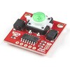
Description。Buttons are an easy and tactile way to interface with your project, but why would you want to deal with debouncing, polling, and wiring up pull-up resistors? The Qwiic Button with built-in green LED simplifies all of those nasty worries away into an easy to use I2C device! Utilizing our Qwiic Connect System, using the button is as simple as connecting cable and loading up some pre-written code!。If you need multiple buttons for your project, fear not! Each button has configurable I2C address, so you can daisy-chain multiple buttons over Qwiic and still address each one individually. We've got an example in our Arduino library that provides super-easy way to configure your Qwiic Button to whatever I2C address you desire. You can download the library through the Arduino library manager by searching 'SparkFun Qwiic Button' or you can get the GitHub repo as .zip file and install the library from there.。In addition to handling blinking and debouncing, the Qwiic Button has configurable interrupts that can be configured to activate upon button press or click. We've also taken the liberty of implementing FIFO queue onboard the Qwiic Button where it keeps an internal record of when the button was pressed. This means that code on your microcontroller need not waste valuable processing time checking the status of the button but instead can run small function whenever the button is pressed or clicked! For more information on interrupts check out our guide here!。The SparkFun Qwiic Connect System is an ecosystem of I2C sensors, actuators, shields and cables that make prototyping faster and less prone to error. All Qwiic-enabled boards use common 1mm pitch, 4-pin JST connector. This reduces the amount of required PCB space, and polarized connections mean you can't hook it up wrong.。Get Started with the SparkFun Qwiic Button Guide。Features。12mm Green LED Button rated for 50mA。Built in LED can be configured for your desired level of blinkiness!。Each button has configurable I2C address。Configurable interrupts check out our guide here!。FIFO queue。Don't like the color green? Check out the SparkFun Qwiic Button Breakout and add another colored button!。Red LED Tactile Button。Blue LED Tactile Button。Green LED Tactile Button。White LED Tactile Button
アズワン品番67-0420-14
1個
¥1,498
税込¥1,648
33日以内出荷

Description。The SparkFun Qwiic LED Stick features ten addressable APA102 LEDs, making it easy to add full color LED control using I2C. Write to individual LEDs to display a count in binary, or write to the whole strip for cool lighting effects. You can even add more LEDs to the end if you need to. We've written an Arduino library and Python package that take care of the I2C and communication to the LEDs so all you have to do is decide what color each LED should be.。The LED Stick has a default I2C address of 0x23 but can be changed with a simple command, allowing you to control up to 100 LEDs(10 Qwiic LED Sticks)on a single bus! The address can also be changed to 0x22 by closing the solder jumper on the back of the board.。This board is one of our many Qwiic compatible boards! Simply plug and go. No soldering, no figuring out which is SDA or SCL, and no voltage regulation or translation required!。Warning:Using a lot of LEDs can draw a lot of current. Make sure to consider the power limits of your setup. If you expect your LED chain to draw more than 600mA of current, connect your external supply directly to VLED. Closing the jumper from VLED to VCC will add a 4.7uF decoupling capacitor.。The SparkFun Qwiic Connect System is an ecosystem of I2C sensors, actuators, shields and cables that make prototyping faster and less prone to error. All Qwiic-enabled boards use a common 1mm pitch, 4-pin JST connector. This reduces the amount of required PCB space, and polarized connections mean you can't hook it up wrong.。Get Started with the Qwiic LED Stick Guide。Features。10x APA102C addressable LEDs driven by an ATTiny85。Default I2C Address:0x23(Adjustable to 0x22 via Jumper)。2x Qwiic Connectors
アズワン品番67-0421-83
1個
¥2,998
税込¥3,298
33日以内出荷

Description。This MI:pro Protector Case for the BBC micro:bit has been designed to work with both the original micro:bit V1 and the micro:bit V2. These cases feature a four-layer construction style with ability to mount a 2xAAA battery pack to the back of the case while still providing access to all buttons and ports on the micro:bit. Though these cases do protect the micro:bit astoundingly well, the biggest benefit of using the MI:pro is to not accidentally short out the pads on the back of the micro:bit.。Construction is simple, requiring only a small flathead screwdriver(at most), and involves layering each plate on top of one another around the micro:bit and screwing it into place. Luckily, the MI:pro Protector case enables easy access to the edge pins at the bottom of the micro:bit, allowing it to still be plugged into an edge connector found on many of our carrier boards. The only board that cannot be used in conjunction with the MI:pro case is the SparkFun gamer:bit due to its edge connector being located in the center of the board.。Note:The MI:pro Protector case only includes the parts found in the Includes Tab. This case does。NOT。include a micro:bit, power source or mounting screws. These items will need to be purchased separately.。Features。Dimensions:Length:65mm.。Width:37mm.。Depth(without screws):12mm.。Depth(with screws):18.5mm.。Provides excellent protection to the BBC micro:bit whilst allowing access to the bottom pins.。Full access to the A and B buttons on the BBC micro:bit.。Attach a battery cage to the rear of the case with the supplied sticky fixer.。Full access to pins and connections including the micro USB connector.。Clear case material shows the on-board LEDs in perfect clarity.。The case is compatible with versions 1 and 2 of the micro:bit.。When used in conjunction with a battery holder, micro:bit projects can be fully mobile.
アズワン品番67-0426-13
1個
¥2,098
税込¥2,308
33日以内出荷

Description。The Mountable MI:pro is a simple and compact protective case for the micro:bit. This case has been specifically designed with portability and expansion in mind and is compatible with both the original micro:bit V1 and the micro:bit V2. These cases feature a three-layer construction style with ability to wall-mount the whole assembly onto any surface you want while still providing access to all buttons and ports on the micro:bit. Though these cases do feature wall-mountable tabs, the biggest benefit of using a case is to not accidentally short out the pads on the back of the micro:bit.。Construction is simple, requiring only a small flathead screwdriver, and involves layering each plate on top of one another around the micro:bit and screwing it into place. Luckily, the MI:pro case enables easy access to the edge pins at the bottom of the micro:bit, allowing it to still be plugged into an edge connector found on many of our carrier boards. The only board that cannot be used in conjunction with the MI:pro case is the SparkFun gamer:bit due to its edge connector being located in the center of the board.。Note:The MI:pro case only includes the parts found in the Includes Tab. This case does NOT include a micro:bit, power source or mounting screws. These items will need to be purchased separately.。Features。Dimensions:Length(minus the mounting brackets on the side):65mm.。Length(with the mounting brackets on the side):91mm.。Width:37mm.。Depth(without screws):9mm.。Depth(with screws):14mm.。Provides excellent protection to the BBC micro:bit whilst allowing access to the bottom pins.。Full access to the A and B buttons on the BBC micro:bit.。The mounting points allow you to fix the micro:bit to a surface for sturdy and more permanent installations.。Full access to pins and connections including the micro USB connector.。Clear case material shows the on-board LEDs in perfect clarity.。The case is compatible with versions 1 and 2 of the micro:bit.
アズワン品番67-0426-14
1個
¥1,798
税込¥1,978
33日以内出荷

。Description。Gone are the days that you have to worry about silicone weather proofing splitting and breaking on you! These are sealed addressable 1 meter long 5V RGB LED strips that come packed with 60 APA104s per meter. Each of these strips are enclosed by a flexible silicon jacket with an IP65 waterproof rating to protect your precious APA104 LEDs. You will be able to control each RGB LED individually giving you the ability to create cool lighting effects for your car, fish tank, or perhaps under cabinet lighting in your kitchen! These LED strips are compatible with similar WS2812 and SK6812 addressable LED's.。Note:。These come in 1m segments on a reel. They are preterminated with 0.1" spaced 3-pin connectors as well as a 2 wire power connector, as shown in the pictures.。Features。Flexible LED strip with external control for each LED pixel。High brightness, full-color and fully addressable(cascade, chasing and scanning)。Maximum length of 5 meters。Example uses include architectural, landscape, and decorative lighting
アズワン品番67-0421-40
1個
¥9,998
税込¥10,998
欠品中

Description。The LIDAR-Lite v4 LED sensor is the next step in the LIDAR-Lite line. A small, lightweight, low-power optical ranging sensor. It's the first to incorporate ANT profile wireless networking technology into an optical sensor. Its built-in nRF52840 processor means that developers can create custom applications, or be operated as a stand-alone device right out of the box by using the preloaded stock application.。Like the LIDAR-Lite v3 and LIDAR-Lite v3HP sensors; it can also be directly connected to an external micro-controller running a custom user application. As such, it provides a highly adaptable option for OEM and maker applications in robotics, Internet of Things, and unmanned vehicles ― or any application where an ultrasonic sensor might otherwise be used. It's perfect as the basic building block for applications where wireless capabilities, small size, light weight, low power consumption and high performance are important factors in a short-range, 10-meter, optical distance measuring sensor.。The LIDAR-Lite v4 requires an external 5VDC power source and soldering is required. This Time-of-Flight ranging module uses a LED and optics for ranging. It does not use a laser; therefore, it is inherently eye-safe under normal usage.。Features。Resolution:1 cm。Measurement repeatability:As measured indoors to a 90% reflective target。1 cm is equivalent to 1 standard deviation。Using "high accuracy" mode, with averaging:+/- 1 cm to 2 meters。+/- 2 cm to 4 meters。+/- 5 cm to 10 meters。Range:5 cm to 10 meters(as measured from back of unit)。Update rate:I2C = >200 Hz typical。ANT(R)= up to 200 Hz to a 90% target indoors at 2m in normal operating mode。Interface:I2C or ANT; user configurable for SPI using the Nordic SDK。Power(operating voltage):4.75 - 5.25 VDC。Current consumption:2mA idle, 85mA during acquisition。Operating temperature:-20 to 60° C。LED wavelength:940 nm。Beam divergence:4.77°。Optical aperture:14.9 mm。Unit size(HxWxD):2.1"×0.8"×0.9"(52.2×21.2×24.0 mm)。Weight:14.6 g(0.5 oz)
アズワン品番67-0427-09
1個
¥20,980
税込¥23,078
33日以内出荷

Description。This is the PICkit 4, the official programmer from Microchip. The PICkit 4 allows debugging and programming of PIC(R), dsPIC(R), AVR, SAM and CEC flash microcontrollers and MPUs using the powerful graphical user interface of the MPLAB X Integrated Development Environment(IDE). The MPLAB PICkit 4 is connected to a PC using a high-speed 2.0 USB interface and can be connected to the target via an 8-pin Single In-Line(SIL)connector. The connector uses two device I/O pins and the reset line to implement in-circuit debugging and In-Circuit Serial Programming(TM)(ICSP(TM)). An additional micro SD card slot and the ability to be self-powered from the target means you can take your code with you and program on the go. Comes with a USB to micro-B USB cable.。Features。Powered by a high-speed USB 2.0, no external power required。Real-time execution。MPLAB X IDE compatible(free copy included)。Built-in over-voltage/short circuit monitor。Firmware upgradeable from PC/web download。Fully enclosed。Target voltage of 1.20V to 5.5V。Can supply up to 50mA of power to the target。Minimal current consumption at <100μA from target。Diagnostic LEDs(power, busy, error)。Read/write program and data memory of microcontroller。Erase of program memory space with verification。Freeze-peripherals at breakpoint。8-pin single in-line header supports advanced interfaces such as 4-wire JTAG and Serial Wire Debug with streaming Data Gateway。Backward compatible for demo boards, headers and target systems using 2-wire JTAG and ICSP
アズワン品番67-0425-08
1個
¥40,980
税込¥45,078
当日出荷

Description。The SN74HC595N is a simple 8-bit shift register IC. Simply put, this shift register is a device that allows additional inputs or outputs to be added to a microcontroller by converting data between parallel and serial formats. Your chosen microprocessor is able to communicate with the The SN74HC595N using serial information then gathers or outputs information in a parallel(multi-pin)format. Essentially it takes 8 bits from the serial input and then outputs them to 8 pins.。This small DIP packaged IC contains an 8-bit, serial-in parallel-out shift register that feeds an 8-bit D-type storage register with parallel 3-state outputs.。Note:。This is a drop-in replacement for the 74HC595 shift register IC and should function just fine in any application the previous version could.。Get started with the Shift Register Guide。Features。8-Bit Serial-In, Parallel-Out Shift。Wide Operating Voltage Range of 2 V to 6 V。High-Current 3-State Outputs Can Drive Up to 15 LSTTL Loads。Low Power Consumption:80-μA。±6-mA Output Drive at 5 V
アズワン品番67-0420-82
1個
¥219
税込¥241
当日出荷

Description。These are your run-of-the-mill 1/4 Watt, +/- 5% tolerance PTH resistors. Commonly used in breadboards and other prototyping applications, these 330 ohm resistors make excellent LED current limiters and are great for general use. These thi
アズワン品番67-0425-49
1個
¥279
税込¥307
33日以内出荷

Description。This is a common 555 timer/oscillator from TI. A classic for all of those first year circuits projects where you need to blink an LED, generate tone, and thousands of other great beginning projects. Google around for a huge list of resourc
アズワン品番67-0421-55
1個
¥309
税込¥340
33日以内出荷

。Description。USB C is quickly becoming more and more prominent in the maker community because, let's be honest, who likes trying three times to insert USB into a port? This FTDI cable is a USB C to Serial converter which allows for a simple way to connect TTL interface devices to USB. Each 26AWG cable is one meter in length with the USB C side protected by a 2in enclosure.。The FTDI cable is designed around an RS232, which is housed in a USB C connector. The other side of the cable is terminated with a 0.1" pitch, 6-pin connector with the following pinout:RTS(Green), RX(Yellow), TX(Orange), VCC 5V(Red), CTS(Brown), GND(Black). This FTDI to USB C Cable is also capable of handling high voltages up to 300V max.。There are pros and cons to the FTDI Cable vs the FTDI Basic. The FTDI Basic has great LED indicators, but requires a Mini-B cable. The FTDI Cable is well protected against the elements, but is large and cannot be embedded into a project as easily. The FTDI Basic uses DTR to cause a hardware reset where the FTDI cable uses the RTS signal.
アズワン品番67-0420-42
1個
¥7,198
税込¥7,918
欠品中

Description。Cherry MX Keyswitches are top-of-the-line mechanical keyboard switches. They're satisfyingly "clicky", reliable up to tens-of-millions of key presses, and a standard in gaming and programming keyboards across the globe. With the SparkFun Cherry MX Switch Breakout we have made the switches more easily adaptable to breadboard or perfboard-based projects. The Cherry MX Switch Breakout is a perfect prototyping tool for projects ranging from a single-key user-input to fully-custom 101-key keyboards.。In addition to breaking out the switch contacts to breadboard-compatible headers, the Cherry MX Switch Breakout also provides access to an optional switch-mounted LED. Plus, the pin break-outs are designed with keyboard matrix-ing in mind, so you can interconnect as many boards as you'd like into a row-column configuration, keeping the I/O-pin requirements as low as possible.。Note:If you are looking for a Cherry MX Switch to use with this breakout, we've got you covered! CLICK HERE!。Get Started with the Cherry MX Switch Guide。Features。Support for 3mm LED。Footprint for LED current-limiting resistor。Footprint for switch-isolating diode。Chain-able in row/column matrices。Designed to match standard key spacing and keyboard row offsets
アズワン品番67-0419-91
1個
¥559
税込¥615
33日以内出荷

Description。This diode-transistor photocouplers consist of an LED, optically coupled to a high speed photodetector to transmit electrical signals between circuits while still isolating your system from higher voltages. The 6N137 optoisolator is presented in an 8-pin DIP package.。The output features is an open collector and coupler parameters are guaranteed over the temperature range from -40℃~5℃. The internal shield provides a guaranteed Common Mode Transient Immunity(typical)10KV/μs.。Features。High Speed:10MBd。Common Mode Rejection:10KV/μs
アズワン品番67-0421-33
1個
¥329
税込¥362
33日以内出荷

。Description。Cherry MX Keyswitches are top-of-the-line mechanical keyboard switches. They're satisfyingly "clicky", reliable up to tens-of-millions of key presses, and a standard in gaming and programming keyboards across the globe. This 'blue' version Cherry MX Switch is favored by most due to its secondary internal actuator making it less likely to "double-tap." If you are looking for a noticeably audible and high-quality key switch, this is the perfect option for you!。Most Cherry MX Switches - including this blue, MX1A-E1NW switch we carry - have a recess in their body designed to fit a small 3mm LED. Additionally, the weighting for this switch is just around 50cN(centi-Newtons).。Note:。If you are looking for an easy way to incorporate this switch to your project, be sure to check out or breakout board! CLICK HERE!。Get Started with the Cherry MX Switch Guide。Features。Contact Form:SPST。Current Rating:10mA。Voltage Rating:12V。Switch Weighting:50cN。3mm LED Slot
アズワン品番67-0420-84
1個
¥379
税込¥417
33日以内出荷

Description。These are the sturdy little stomp switches that you find on guitar effects pedals. They're 3PDT(three-pole, double-throw)type switches. These switches allow you to modify your effects for true bypass and lets you wire a status indicator LED. This is useful for stage performers, as it leaves no question if the "box" is on or off.。These are the same Stomp Switches found in our Proto Pedal Kit. Use these as replacements in some types of effects pedals or, better yet, build your own!
アズワン品番67-0421-36
1個
¥1,298
税込¥1,428
33日以内出荷

Description。The micro:bit v2 Educator's Lab Pack includes 10 micro:bit v2 boards and everything you need to get you started with the new learning platform. The Lab Pack has everything you need, including micro:bits, cables, battery packs and a few parts to experiment with. This package provides an easy way to introduce your students to the micro:bit without any difficulty or parts hunting.。SparkFun packages everything educators need to get started with the micro:bit in a variety of classroom settings and learning environments. The hardware boards, cables and extra parts come pre-packaged. Examples and curriculum materials are available from SparkFun and micro:bit, as well as from other educators involved in this growing maker education movement.。Lab Packs are your classroom entry point. By combining our kits, popular boards and other educational tools with support materials(to be updated), SparkFun brings all the power of the open source community to the classroom. We've also updated the battery pack to be closer to what is in other micro:bit kits. It now requires 2xAAA batteries.。The micro:bit is a pocket-sized computer that lets you get creative with digital technology. Between the micro:bit and our shield-like bit boards you can do almost anything while coding, customizing and controlling your micro:bit from almost anywhere! You can use your micro:bit for all sorts of unique creations, from robots to musical instruments and more. At half the size of a credit card, this versatile board has vast potential!。。Features。Micro:bit 2.0:64 MHz Arm Cortex-M4 with FPU。512KB Flash。128KB RAM。5x5 Red LED Array。Two Programmable Buttons, one touch sensitive logo。MEMS microphone and LED indicator。Onboard Light, Compass, Accelerometer, Temp Sensors and Speaker。2.4 Ghz Micro:bit Radio/BLE 5.0 Smart Antenna。25-pin Edge Connector。4 dedicated GPIO, PWM, i2c, SPI, and ext. power。Three Digital/Analog Input/Output Rings。Two Power Rings --- 3V and GND。Dedcated I2C bus for peripherals。MicroUSB Connector(5V)。JST-PH Battery Connector(。Not。JST-XH)(3V)。Power/reset Button with Status LED。200 mA available for accessories。Program with C++, MakeCode, Python, Scratch
アズワン品番67-0424-92
1個
¥99,980
税込¥109,978
33日以内出荷

Description。The SparkFun Thing Plus - RP2040 is a low-cost, high performance board with flexible digital interfaces featuring the Raspberry Pi Foundation's RP2040 microcontroller. Besides the Thing Plus or。Feather。footprint(with 18 GPIO pins), the board also includes an SD card slot, 16MB(128Mbit)flash memory, a JST single cell battery connector(with a charging circuit and fuel gauge sensor), an addressable WS2812 RGB LED, JTAG PTH pins, four(4-40 screw)mounting holes, and our signature Qwiic connector.。The RP2040 contains two ARM Cortex-M0+ processors(up to 133MHz)and features:264kB of embedded SRAM in six banks。6 dedicated IO for SPI Flash(supporting XIP)。30 multifunction GPIO:Dedicated hardware for commonly used peripherals。Programmable IO for extended peripheral support。Four 12-bit ADC channels with internal temperature sensor(up to 0.5 MSa/s)。USB 1.1 Host/Device functionality。The RP2040 is supported with both C/C++ and MicroPython cross-platform development environments, including easy access to runtime debugging. It has UF2 boot and floating-point routines baked into the chip. While the chip has a large amount of internal RAM, the board includes an additional 16MB of external QSPI flash memory to store program code.。The SparkFun Qwiic Connect System is an ecosystem of I2C sensors, actuators, shields and cables that make prototyping faster and less prone to error. All Qwiic-enabled boards use a common 1mm pitch, 4-pin JST connector. This reduces the amount of required PCB space, and polarized connections mean you can't hook it up wrong.。Get Started With the Thing Plus RP2040 Hookup Guide。Features。SparkFun Thing Plus - RP2040 Features。Raspberry Pi Foundation's RP2040 microcontroller。16MB QSPI Flash Memory。JTAG PTH Pins。Thing Plus(or Feather)Form-Factor:18[1]x Multifunctional GPIO Pins[2]。Four available 12-bit ADC channels with internal temperature sensor(500kSa/s)。Up to eight 2-channel PWM。Up to two UARTs。Up to two I2C buses。Up to two SPI buses。USB-C Connector:USB 1.1 Host/Device functionality。2-pin JST Connector for a LiPo Battery。(not included)。500mA charging circuit。Qwiic Connector。Buttons:Boot。Reset。LEDs:PWR。- Red 3.3V power indicator。CHG。- Yellow battery charging indicator。25。- Blue status/test LED(。GPIO 25。)。WS2812。- Addressable RGB LED(。GPIO 08。)。Four Mounting Holes:4-40 screw compatible。Dimensions:2.3"×0.9"。RP2040 General Features。Dual Cortex M0+ processors, up to 133 MHz。264 kB of embedded SRAM in 6 banks。6 dedicated IO for QSPI flash, supporting execute in place(XIP)。30 programmable IO for extended peripheral support。SWD interface。Timer with 4 alarms。Real time counter(RTC)。USB 1.1 Host/Device functionality。Supported programming languages。MicroPython。C/C++。1.。Note:。GPIO 08。is not included in this count, as it passes through the WS2812 addressable RGB LED first.。GPIO 07。and。GPIO 23。are counted as a single GPIO because they are tied together.。2.。Note:The GPIO pins are programmable so you can reconfigure the pins! Check out the RP2040 datasheet for more information on the GPIO functionality.
アズワン品番67-0423-56
1個
¥6,698
税込¥7,368
33日以内出荷

Description。The TFMini Plus is a ToF(Time of Flight)LiDAR sensor capable of measuring the distance to an object as close as 10 centimeters(+/- 5cm up to 6m)and as far as 12 meters(+/-1% starting at 6m)! As with all LiDAR sensors, your effective detection distance will vary depending on lighting conditions and the reflectivity of your target object, but what makes this sensor special is its size. Measuring only 35x18.5x21mm, the TFMini Plus allows you to integrate LiDAR into applications traditionally reserved for smaller sensors.。Setting itself apart from the original TFmini, the TFmini Plus has been designed with an IP65 enclosure meaning its "Dust tight water resistant", and also passed the vibration test of drone level, which will greatly expand its application range. The TFMini Plus is easy to power at only 5V and easy to talk to using the UART communication protocol.。Important:This product does not use laser light for ranging. Instead it contains an LED and optics. Many such systems are being marketed under the name "LiDAR," although it may be more appropriate to think of this device as a "Time-of-Flight Infrared Rangefinder". It differs significantly from traditional IR rangefinders in that it uses ToF to determine range and not triangulation ― as is performed by the Sharp GP-series devices.。Features。Operating Range - 0.1m~12m1。Accuracy - ±5cm@(0.1-6m), ±1%@(6m-12m)。Distance resolution - 5mm。Frame rate - 1-1000Hz(adjustable)。Ambient light immunity - 70klux。Operating temperature - -20℃~60℃。Enclosure rating - IP65。Light source - LED。Central wavelength - 850nm。FOV - 3.6°。Supply voltage - 5V±0.5V。Average current - ≦110mA。Power consumption - 550mW。Peak current - 500mA。Communication level - LVTTL(3.3V)。Material of enclosure - ABS+PC。Storage temperature - -20℃~75℃。Weight - 11g。Wire length - 30cm
アズワン品番67-0426-94
1個
¥28,980
税込¥31,878
欠品中

Description。Do you own micro:bit or micro:bit Go Bundle and want to expand your skills with the new microcontroller? You are in luck! The SparkFun Inventor's Kit Bridge Pack for micro:bit was designed to provide you with an easy way to transform your m:b into full fledged learning kit! Each Bridge Pack includes all of the parts found in the SIK for micro:bit that aren't included with the Go Bundle. With the SIK Bridge Pack for micro:bit you will be able to complete circuits that will teach you how to read sensors, move motors, build Bluetooth(R)devices and more.。The micro:bit is pocket-sized computer that lets you get creative with digital technology. Between the micro:bit and our shield-like bit boards you can do almost anything while coding, customizing and controlling your micro:bit from almost anywhere! You can use your micro:bit for all sorts of unique creations, from robots to musical instruments and more. At half the size of credit card, this versatile board has vast potential!。Note:The Bridge Pack is NOT full SparkFun Inventor's Kit and only includes the parts to complement micro:bit Go Bundle or standalone board. That also means that this kit does。not。include micro:bit, which will need to be purchased separately.。Get started with the micro:bit SIK Experiment Guide。Examples。Circuit 0:Hello, micro:bit!。Circuit 1:Blinking an LED。Circuit 2:Reading Potentiometer。Circuit 3:Reading Photoresistor。Circuit 4:Driving an RGB LED。Circuit 5:Reading an SPDT Switch。Circuit 6:Reading Button Press。Circuit 7:Reading the Temperature Sensor。Circuit 8:Using Servo Motor。Circuit 9:Using Buzzer。Circuit 10:Using the Accelerometer。Circuit 11:Using the Compass
アズワン品番67-0424-21
1個
¥13,980
税込¥15,378
33日以内出荷

Description。The SparkFun Inventor's Kit(SIK)for micro:bit v2 is a great way to get creative, connected and coding with the micro:bit. The SIK for micro:bit v2 provides not only the micro:bit v2 board but everything you need to hook up and experiment with multiple electronic circuits! With the SIK for micro:bit v2 you will be able to complete circuits that will teach you how to read sensors, move motors, build Bluetooth(R)devices and more.。The SparkFun Inventor's Kit for micro:bit is the latest and greatest in single-board computer kits. Surrounding the micro:bit v2 SIK is one core philosophy --- that anyone can(and should)experiment with cutting-edge electronics in a fun and playful way without breaking the bank.。The kit does not require any soldering and is recommended for all users, from beginners to engineers. We have provided a complete Experiment Guide in the Documents tab for you to check out now! If you have ever been interested in learning about electronics, or if you have used the original SparkFun Inventor's Kit and are looking for something new, the SIK for micro:bit is the perfect kit for you!。The micro:bit is a pocket-sized computer that lets you get creative with digital technology. Between the micro:bit and our shield-like bit boards you can do almost anything while coding, customizing and controlling your micro:bit from almost anywhere! You can use your micro:bit for all sorts of unique creations, from robots to musical instruments and more. At half the size of a credit card, this versatile board has vast potential!。。Examples。Circuit 0:Hello, micro:bit!。Circuit 1:Blinking an LED。Circuit 2:Reading a Potentiometer。Circuit 3:Reading a Photoresistor。Circuit 4:Driving an RGB LED。Circuit 5:Reading an SPDT Switch。Circuit 6:Reading a Button Press。Circuit 7:Reading the Temperature Sensor。Circuit 8:Using a Servo Motor。Circuit 9:Using a Buzzer。Circuit 10:Using the Accelerometer。Circuit 11:Using the Compass
アズワン品番67-0424-61
1個
¥15,980
税込¥17,578
33日以内出荷

Description。The A0 in the latest in Macchina's line of OBD-II interfaces. The A0 uses the power of the ESP32 BLE and WiFi module to allow for wireless access to the OBD-II port most modern cars have.。The Macchina A0 module plugs directly into the OBD-II port found in most modern cars and receives its power from the port. From there, one can interface with the device through a few different methods. The easiest is with software such as SavvyCAN, Torque Lite on Android. Besides getting all on board diagnostic information, you're able to control certain aspects of the car and create cool projects such as dash-mounted, shift lights. The A0 can also be programmed in the Arduino IDE, so there's plenty of possibilities to customize the device for what you want to do with your car!。Features。ODB-II compatibility with all modern cars(1996 or newer)。Pre-loaded with SavvyCAN for plug and play(wireless!)reverse engineering。WiFi and Bluetooth(R)Functionality。ESP32 Processor。Super bright RGB LED。CAN Communication Functionality。Programmable with the Arduino IDE
アズワン品番67-0423-39
1個
¥28,980
税込¥31,878
33日以内出荷

。Description。The SparkFun Inventor's Kit(SIK)for Arduino Uno is a great way to get started with programming and hardware interaction with the Arduino programming language. The SIK includes everything you need to complete five overarching projects consisting of 16 interconnected circuits that teach everything from blinking an LED to reading sensors. The culminating project is your very own autonomous robot! No previous programming or electronics experience is required to use this kit.。The online guide contains step-by-step instructions with circuit diagrams and hookup tables for building each project and circuit with the included parts. Full example code is provided, new concepts and components are explained at point of use, and troubleshooting tips offer assistance if something goes wrong.。The kit does not require any soldering and is recommended for beginners ages 10 and up who are looking for an Arduino starter kit. For SIK version 4.1 we took an entirely different approach to teaching embedded electronics. In previous versions of the SIK, each circuit focused on introducing a new piece of technology. With SIK v4.1, components are introduced in the context of the circuit you are building, and each circuit builds upon the last, leading up to a project that incorporates all of the components and concepts introduced throughout the guide. With new parts and a completely new strategy, even if you've used the SIK before, you're in for a brand-new experience!。This version of the SIK replaces the SparkFun RedBoard Qwiic with the Arduino Uno(SMD version)and comes without the SIK guidebook and carrying case. With these components being swapped and removed, we were able to reduce the overall size and weight of the kit, making shipping cheaper and easier for anyone ordering internationally.。Note:As stated above, this SIK does NOT include a carrying case or print guidebook.。Get Started With the SparkFun Inventor's Kit v4.1 Experiment Guide。Examples。Project 1:Light。Circuit 1A:Blinking an LED。Circuit 1B:Potentiometer。Circuit 1C:Photoresistor。Circuit 1D:RGB Night-Light。Project 2:Sound。Circuit 2A:Buzzer。Circuit 2B:Digital Trumpet。Circuit 2C:"Simon Says" Game。Project 3:Motion。Circuit 3A:Servo Motors。Circuit 3B:Distance Sensor。Circuit 3C:Motion Alarm。Project 4:Display。Circuit 4A:LCD "Hello, World!"。Circuit 4B:Temperature Sensor。Circuit 4C:"DIY Who Am I?" Game。Project 5:Robot。Circuit 5A:Motor Basics。Circuit 5B:Remote-Controlled Robot。Circuit 5C:Autonomous Robot
アズワン品番67-0424-34
1個
¥28,980
税込¥31,878
33日以内出荷

Description。The SparkFun Alphanumeric Display Arduino library makes printing strings to the display as easy as calling the print()function. With this library, you'll be able to send I2C commands to the VK16K33 LED driver chip to light up segments(including the decimal point or colon)and even scroll your string across the display. You can download the library through the Arduino library manager by searching 'SparkFun Alphanumeric Display' or you can get the GitHub repo as a .zip file and install the library from there.。The SparkFun Qwiic Connect System is an ecosystem of I2C sensors, actuators, shields and cables that make prototyping faster and less prone to error. All Qwiic-enabled boards use a common 1mm pitch, 4-pin JST connector. This reduces the amount of required PCB space, and polarized connections mean you can't hook it up wrong.。Get Started with the Qwiic Alphanumeric Display Hookup Guide。Features。Operating Voltage:3.3V。Integrated RC oscillator。Maximum display segment numbers:128 patterns。13×3 matrix key scan circuit。16-step dimming circuit。I2C Addresses:0x70(0x71, 0x72, 0x73)。2x Qwiic connectors。2x Wall Mounting Points
アズワン品番67-0421-61
1個
¥2,298
税込¥2,528
33日以内出荷

Description。The SparkFun Alphanumeric Display Arduino library makes printing strings to the display as easy as calling the print()function. With this library, you'll be able to send I2C commands to the VK16K33 LED driver chip to light up segments(including the decimal point or colon)and even scroll your string across the display. You can download the library through the Arduino library manager by searching 'SparkFun Alphanumeric Display' or you can get the GitHub repo as a .zip file and install the library from there.。The SparkFun Qwiic Connect System is an ecosystem of I2C sensors, actuators, shields and cables that make prototyping faster and less prone to error. All Qwiic-enabled boards use a common 1mm pitch, 4-pin JST connector. This reduces the amount of required PCB space, and polarized connections mean you can't hook it up wrong.。Get Started with the Qwiic Alphanumeric Display Hookup Guide。Features。Operating Voltage:3.3V。Integrated RC oscillator。Maximum display segment numbers:128 patterns。13×3 matrix key scan circuit。16-step dimming circuit。I2C Addresses:0x70(0x71, 0x72, 0x73)。2x Qwiic connectors。2x Wall Mounting Points
アズワン品番67-0421-62
1個
¥2,298
税込¥2,528
33日以内出荷

Description。The SparkFun Alphanumeric Display Arduino library makes printing strings to the display as easy as calling the print()function. With this library, you'll be able to send I2C commands to the VK16K33 LED driver chip to light up segments(including the decimal point or colon)and even scroll your string across the display. You can download the library through the Arduino library manager by searching 'SparkFun Alphanumeric Display' or you can get the GitHub repo as a .zip file and install the library from there.。The SparkFun Qwiic Connect System is an ecosystem of I2C sensors, actuators, shields and cables that make prototyping faster and less prone to error. All Qwiic-enabled boards use a common 1mm pitch, 4-pin JST connector. This reduces the amount of required PCB space, and polarized connections mean you can't hook it up wrong.。Get Started with the Qwiic Alphanumeric Display Hookup Guide。Features。Operating Voltage:3.3V。Integrated RC oscillator。Maximum display segment numbers:128 patterns。13×3 matrix key scan circuit。16-step dimming circuit。I2C Addresses:0x70(0x71, 0x72, 0x73)。2x Qwiic connectors。2x Wall Mounting Points
アズワン品番67-0421-64
1個
¥2,398
税込¥2,638
33日以内出荷

Description。The SparkFun Alphanumeric Display Arduino library makes printing strings to the display as easy as calling the print()function. With this library, you'll be able to send I2C commands to the VK16K33 LED driver chip to light up segments(including the decimal point or colon)and even scroll your string across the display. You can download the library through the Arduino library manager by searching 'SparkFun Alphanumeric Display' or you can get the GitHub repo as a .zip file and install the library from there.。The SparkFun Qwiic Connect System is an ecosystem of I2C sensors, actuators, shields and cables that make prototyping faster and less prone to error. All Qwiic-enabled boards use a common 1mm pitch, 4-pin JST connector. This reduces the amount of required PCB space, and polarized connections mean you can't hook it up wrong.。Get Started with the Qwiic Alphanumeric Display Hookup Guide。Features。Operating Voltage:3.3V。Integrated RC oscillator。Maximum display segment numbers:128 patterns。13×3 matrix key scan circuit。16-step dimming circuit。I2C Addresses:0x70(0x71, 0x72, 0x73)。2x Qwiic connectors。2x Wall Mounting Points
アズワン品番67-0421-63
1個
¥2,298
税込¥2,528
33日以内出荷

Description。The SparkFun MicroMod Environmental Function Board adds additional sensing options to the MicroMod Processor Boards. This Function Board includes three sensors to monitor air quality(SGP40), humidity temperature(SHTC3), and CO2 concentrations(STC31)in your indoor environment. To make it even easier to use, all communication is over the MicroMod's I2C bus!。The SGP40 measures the quality of the air in your room or house. The SGP40 uses a metal oxide(MOx)sensor with a temperature controlled micro hotplate and provides a humidity-compensated volatile organic compound(VOC)based indoor air quality signal. Both the sensing element and VOC Algorithm feature an unmatched robustness against contaminating gases present in real world applications enabling a unique long term stability as well as low drift and device to device variation.。The SHTC3 is a highly accurate digital humidity and temperature sensor. The SHTC3 uses a capacitive humidity sensor with a relative humidity measurement range of 0 to 100% RH and bandgap temperature sensor with a temperature measurement range of -40℃ to 125℃. The SHTC3 builds on the success of their SHTC1 sensor with higher accuracy(±2% RH, ±0.2℃)than its predecessor, enabling greater flexibility.。The STC31 measures CO2 concentrations based on thermal conductivity and has two CO2 measurement ranges:0 to 25 vol%; and 0 to 100 vol%. The measurement repeatability is 0.2 vol%, with a stability of 0.025 vol% / ℃. The measurement accuracy depends on the measurement range:0.5 vol% + 3% measured value; 1 vol% + 3% measured value. Using measurements from the SHTC3, the STC31 is able to provide humidity-compensated measurements together with improved temperature compensation. The STC31 can compensate for atmospheric pressure too - which is handy if, like us, you're up in the mountains!。The outstanding performance of these three sensors is based on Sensirion's patented CMOSens(R)technology, which combines the sensor element, signal processing, and digital calibration on a small CMOS chip. The well-proven CMOS technology is perfectly suited for high-quality mass production and is the ideal choice for demanding and cost-sensitive OEM applications.。Utilizing our handy M.2 MicroMod connector, no soldering is required to connect it to your system. Simply match up the key on your processor and function board's beveled edge connector to their respective key on the M.2 connector, then secure them to the main board with screws. The MicroMod Environmental Function Board can then be read via the I2C port. The board is equipped with the AP2112 3.3V voltage regulator, I2C pull-up resistors, power LED, jumper to disable the LED, and jumpers for alternative STC31 addresses.。Note:A MicroMod Processor and Main Board are not included with this MicroMod Environmental Function Board. These boards will need to be purchased separately.。MicroMod is a modular interface ecosystem that connects a microcontroller "processor board" to various "carrier board" peripherals. Utilizing the M.2 standard, the MicroMod standard is designed to easily swap out processors and function boards on the fly. Pair a specialized carrier board for the project you need with your choice of compatible processor!。Get Started with the MicroMod Environmental Function Board。Features。Input voltage range。2.5V to 6.0V。Typ.。5V。via Main Board's USB connector。Typ.。~3.7V to 4.2V。via Main Board's LiPo battery Connector。I/O voltage。3.3V。AP2112 3.3V voltage regulator(rated 600mA)。Power LED。I2C pull-up resistors。Sensirion SGP40 Air Quality Sensor。Uses I2C interface。Address:0x59(default)。Operating voltage range。1.7V to 3.6V(Typ.。3.3V。)。Operating temperature range。-20℃ to +55℃。Typical current consumption。2.6mA。during continuous operation(at 3.3V)。34μA。when idle(heater off)。Output signal。Digital raw value(SRAW):0 - 65535 ticks。Digital processed value(VOC Index):0 - 500 VOC index points。Switch-on behavior。Time until reliably detecting VOC events:<60s。Time until specifications are met:<1h。Recommended sampling interval。VOC Index:1s。SRAW:0.5s - 10s(Typ. 1s)。Sensirion SHTC3 Humidity and Temperature Sensor。Uses I2C interface。Address:0x70(default, non-configurable)。Operating voltage range。1.62V - 3.6V(Typ.。3.3V。)。Operating temperature range。-40℃ to +125 ℃。Relative Humidity。Measurement range:0% to 100%。Typical accuracy:±2 %RH。Resolution:0.01 %RH。Temperature。Measurement range:-40℃ to +125 ℃。Typical accuracy:±0.2 ℃。Resolution:0.01 ℃。Typical current consumption(varies based on mode)。4.9μA to 430μA(Normal Mode)。0.5μA to 270μA(Low Power Mode)。Allows the STC31 to compensate for humidity and temperature。Sensirion STC31 CO2 Sensor。Uses I2C interface。Addresses:0x29(default)。, 0x2A, 0x2B, 0x2C。Operating voltage range。2.7V to 5.5V(Typ.。3.3V。)。Operating temperature range。-20 ℃ to +85 ℃。Calibrated for CO2 in N2 and CO2 in air。Measurement ranges。0 to 25 vol% in N2。0 to 100 vol% in air。Accuracy。0.5 vol% + 3% measured value in N2。1 vol% + 3% measured value in air。Concentration and temperature resolution:16-bit。Repeatability:0.2 vol%。Temperature stability:0.025 vol% / ℃。Start-up time:14 ms。Thermal conductivity sensor provides calibrated gas concentration and temperature output。Jumpers。PWR LED。I2C pull-up resistors。STC31 address selection。Note:The I2C addresses that are reserved for each sensor is 0x59(SGP40), 0x70(SHTC3), 0x29(STC31). A multiplexer/Mux is required to communicate to multiple SHTC3 sensors on a single bus. The SHTC3 uses the same address as the Qwiic Mux(0x70). For advanced users that are using multiple SHTC3's with the Qwiic Mux, you will need to adjust the Qwiic Mux's default address.
アズワン品番67-0427-60
1個
¥41,980
税込¥46,178
33日以内出荷

Here is a very simple breadboard power supply kit that takes power from a DC wall wart and outputs a selectable 5V or 3.3V regulated voltage. The .1" headers are mounted on the bottom of the PCB for simple insertion into a breadboard. Pins labeled VCC and GND plug directly into the power lines. The lone pair of pins have no electrical connection but help support the PCB.。There are two pins available within the barrel jack footprint. Any stripped +/- DC supply can be connected instead of the barrel connector. Board has both an On/Off switch and a voltage select switch(3.3V/5V).。Comes as a bag of parts kit and is easily assembled if you can follow the silkscreen indicators and have beginning experience with a soldering iron. You will need to read the resistor bands or use a multimeter to determine the resistor sizes.。Dimensions:1.25x1.25"。Kit Includes:DC Barrel Connector(2.1mm center positive)。TO-220 Voltage Regulator(LM317 1.5A max current)。1N4004 Reverse Protection Diode。100uF 25V Capacitor。10uF 25V Capacitor。0.1uF 50V Capacitor。Red Power LED - High Brightness。2×SPDT Slide Switch。4×0.1" Header Pins。2×330 Resistor 1/6W。390 Resistor 1/6W。240 Resistor 1/6W。Bare PCB with Silkscreen Indicators。PTC resettable fuse
仕様●項目1:組込み(組立てキット)●項目2:電源●項目4:リニア電源●項目8:ブレッドボード用電源
アズワン品番67-0454-01
1個
¥3,598
税込¥3,958
33日以内出荷

Description。The LilyMini ProtoSnap is a great way to get started learning about creating interactive e-textile circuits before you start sewing. Like other LilyPad ProtoSnap boards, the LilyMini ProtoSnap has all of its pieces wired together out of the box, enabling you to test the circuit's function before you sew. At the center of the board is a pre-programmed LilyMini microcontroller connected to a LilyPad Light Sensor, LilyPad Button and two pairs of LilyPad LEDs.。The LilyMini ProtoSnap ships with pre-loaded code that uses all the LilyPad pieces connected to it. This sample code has three modes, which can be selected by pressing the LilyPad Button on the bottom-left side of the ProtoSnap. The built-in RGB LED on the LilyMini will change color to indicate which mode has been selected:。White:。All LEDs on.。Magenta:。LEDs fade in and out in a breathing pattern. When the light sensor is covered, LEDs fade faster.。Cyan:。LEDs off. When the light sensor is covered, LEDs will twinkle.。The LilyMini board, at the center of the ProtoSnap, has a built-in battery holder for a CR2032 battery(included). On the opposite side of the LilyMini you will find the SAMD11 brain, which controls the ProtoSnap.。Note:。A portion of this sale is given back to Dr. Leah Buechley for continued development and education in e-textiles.。Note:。The LilyPad LilyMini ProtoSnap does NOT include sewing needles or conductive thread. These items will need to purchased separately.。Warning:You cannot reprogram this product and any attempt at programming is at your own risk!。Get Started with the LilyMini ProtoSnap Guide
アズワン品番67-0422-40
1個
¥5,198
税込¥5,718
33日以内出荷

Description。The SparkFun TFT LCD Breakout is a versatile, colorful, and easy way to experiment with graphics or create a user interface for your project. With a 4-wire SPI interface and microSD card holder, you can use this breakout to easily add visual display/interface capabilities to a project as well as providing all the storage you might need for multimedia files.。To get started with this breakout, you will need an Arduino compatible microcontroller of your choice - we recommend something with extra RAM like the SparkFun Thing Plus. The breakout can be powered with either 5V or 3.3V. The microSD card holder is connected to the same SPI bus as the display which keeps the required pin count low and exists to relieve the burden from your microcontroller's poor memory due to having to store hundreds of images of cats, or really whatever you want to keep there. We have also gone ahead and tricked out the SparkFun HyperDisplay library with a driver made especially for this breakout!。Out of the box, the SparkFun TFT LCD Breakout will come with a large backing PCB that makes it easy to securely mount the display in a project. If you need a more flexible solution you can remove the display module, snap off half the backing board, and then re-insert the display module. When this is done you'll be left with the bare minimum frame around the display to more seamLessly integrate with your project.。Get Started With the SparkFun TFT LCD Breakout Guide。Features。128×160 RGB pixels。Up to 18 bit configurable color depth。2x PWM controllabele LED backlight。microSD Card Slot。V-Score for Minimal Footprint Setup
アズワン品番67-0424-97
1個
¥9,698
税込¥10,668
33日以内出荷

。Description。The SparkFun MicroMod Update Tool is built to interface with the MicroMod Asset Tracker Carrier Board and also makes it simple to communicate directly with the u-blox SARA-R510M8S module using u-blox's sophisticated m-center cellular evaluation software. If you're familiar with u-center, u-blox's GNSS evaluation software, you'll know how excellent their software is. m-center is every bit as good. Attach a USB-C cable and away you go!。The Update Tool is not a full MicroMod Processor Board, it is much simpler than that. It has a CH340C USB-Serial converter on it which gives you full access to all eight pins of the SARA-R5's UART interface via the Asset Tracker's USB-C connector. Think of it as a bridge from USB to serial.。The Update Tool features eight pairs of Plated Through Hole connections for the UART signals. You can use these to connect directly to the SARA UART using 3.3V signals if you want to. The split pads on the rear of the Tool can be opened to isolate the CH340C completely; the pins nearest the M.2 will link straight to the SARA UART.。Get Started with the MicroMod Update Tool Hookup Guide。Features。CH340C USB-Serial converter。Eight pairs of Plated Through Hole connections with split pad jumper links for:Serial Transmit(TX)。Serial Receive(RX)。Request To Send(RTS)。Clear To Send(CTS)。Data Terminal Ready(DTR)。Data Set Ready(DSR)。Ring Indicator(RI)。Data Carrier Detect(DCD)。LED indicator for:Power(3.3V)
アズワン品番67-0423-52
1個
¥1,498
税込¥1,648
33日以内出荷

Description。Are you low on I/O? No problem! The SX1509 Breakout is 16-channel GPIO expander with an I2C interface that means with just two wires, your microcontroller can interface with 16 fully configurable digital input/output pins. But the SX1509 can do so much more than just simple digital pin control. It can produce PWM signals, so you can dim LEDs. It can be set to blink or even breathe pins at varying rates. This breakout is similar to multiplexer or "mux," in that it allows you to get more IO from less pins. And, with built-in keypad engine, it can interface with up to 64 buttons set up in an 8x8 matrix.。Two headers at the top and bottom of the breakout board function as the input and control headers to the board. This is where you can supply power to the SX1509, and where your I2C signals SDA and SCL will terminate. GPIO and power buses are broken out in every-which direction, and configurable jumpers cover most of the rest of the board.。Since the I/O banks can operate between 1.2V and 3.6V(5.5V tolerant)independent of both the core and each other, this device can also work as level-shifter. The SX1509 breakout makes it easy to prototype so you can add more I/O onto your Arduino or I/O limited controller. We've even spun up an Arduino Library to get you started!。Features。Enable Direct Level Shifting Between I/O Banks and Host Controller。5.5V Tolerant I/Os, Up to 15mA Output Sink on All I/Os。Integrated LED Driver with Intensity Control。On-Chip Keypad Scanning Engine Supports Up to 8x8 Matrix(64 Keys)。16 Channels of True Bi-directional Style I/O。400kHz I2C Compatible Slave Interface
アズワン品番67-0419-88
1個
¥2,098
税込¥2,308
33日以内出荷

Description。Your 5V system can wield great power with this big, beefy relay board. How does 10A on the NC contacts and 20A on the NO contacts at 220VAC sound? The SparkFun Beefcake Relay Control Kit contains all the parts you need to get your high-power load under control. Only minimal assembly is required!。The heart of the board is sealed, SPDT 20A/10A Relay. The relay is controlled by 5V logic through transistor, and an LED tells you when the relay is closed. This is kit, so it comes as through-hole parts with assembly required, which makes for some nice soldering practice. Screw terminal connectors on either side of the board make it easy to incorporate into your project.。There are some pretty beefy traces connecting the relay to the load pins, but the 3-pin terminals are only rated for 15A max! If you plan on connecting larger load, you'll need to solder directly to the board. As always with high current and voltage, play it safe and use your judgment when deciding how much of load you want to put on board -- in open airflow the PCB can handle the full 20A for few minutes at time, but in an enclosed area heat can build up.。Note:Please keep in mind that this board is really meant for someone with experience and good knowledge of electricity. If you're uncomfortable soldering or dealing with high voltage, please check out the IoT Power Relay. The IoT Power Relay is fully enclosed, making it lot safer.。Get Started With the Beefcake Hookup Assembly Guide。Features。Voltage Rating:220VAC/28VDC。VCC requirements:4-6V, 150mA capable。SPDT pins exposed(Form C)。14 AWG screw terminals for relay connections.。10 AWG solder lugs for relay connections.。Flyback diode included。Zener recovery diode included(decreases turn-off time)。Heavy oz. copper on PCB
アズワン品番67-0424-03
1個
¥2,898
税込¥3,188
33日以内出荷

Description。The TFMini-S Micro LiDAR Module is a ToF(Time of Flight)LiDAR sensor capable of measuring the distance to an object as close as 10 centimeters(+/- 6cm up to 6m)and as far as 12 meters(+/-1% starting at 6m)! As with all LiDAR sensors, your effective detection distance will vary depending on lighting conditions and the reflectivity of your target object, but what makes this sensor special is its size. Measuring only 42x15x16mm, the TFMini-S allows you to integrate LiDAR into applications traditionally reserved for smaller sensors.。TFMini-S is a single-point ranging LiDAR based on TFmini upgrade. The blind zone is shortened to 10cm, the outdoor performance and accuracy of different reflectivity are improved, it can achieve stable, accuracy, sensitive and high frequency range detection.。Important:This product does not use laser light for ranging. Instead it contains an LED and optics. Many such systems are being marketed under the name "LiDAR," although it may be more appropriate to think of this device as a "Time-of-Flight Infrared Rangefinder". It differs significantly from traditional IR rangefinders in that it uses ToF to determine range and not triangulation ― as is performed by the Sharp GP-series devices.。Features。Operating Range:0.1m~12m@90%Reflectivity。0.1~7m@10% Reflectivity。0.1m~12m@90%Reflectivity(70Klux)。0.1~7m@10% Reflectivity(70Klux)。Accuracy:±6cm@(0.1-6m)。±1%@(6m-12m)。Distance Resolution:1cm。Frame Rate:100Hz。Ambient light immunity:70Klux。Operating Temperature:0℃~60℃。Light source:VCSEL。Central wavelength:850nm。Photobiological safety:Class1(EN60825)。FOV:2°2。Supply voltage:5V±0.1V。Average current:≦140mA。Power consumption:≦0.7W。Peak current:200mA。Communication level:LVTTL(3.3V)。Communication interface:UART / I2C。Dimension:42mmx15mmx16mm(LxWxH)。Housing:PC/ABS。Storage temperature:-20℃~75℃。Weight:5g±0.3g。Cable length:10cm
アズワン品番67-0427-33
1個
¥21,980
税込¥24,178
欠品中

。Description。The SparkFun ESP8266 Thing Starter Kit is a great place to start learning about the Internet of Things(IoT)! Inside this kit you will find a ESP8266 Thing, a Serial Basic Breakout to program it(and USB cable), jumper wires, breadboard, LEDs, and plenty of headers. We've also included a pair of stackable 10-pin headers as well as 40 regular headers to connect your Serial Basic Breakout to the Thing or breadboard. If you have ever been interested in learning about IoT, Arduino, and wireless solutions, the SparkFun ESP8266 Thing Starter Kit is a perfect place to start!。The SparkFun ESP8266 Thing is a breakout and development board for the ESP8266 WiFi SoC - a leading platform for Internet of Things(IoT)or WiFi-related projects. The Thing is low-cost and easy to use, and Arduino IDE integration can be achieved in just a few steps. We've made the ESP8266 easy to use by breaking out all of the module's pins, adding a LiPo charger, power supply, and all of the other supporting circuitry it requires.。Why the name? We lovingly call it the "Thing" due to it being the perfect foundation for your Internet of Things project. The Thing does everything from turning on an LED to posting data with datastream, and can be programmed just like any microcontroller. You can even program the Thing through the Arduino IDE by installing the ESP8266 Arduino addon.。Note:You may want to either use a second USB cable to power the board while programming or connect the solder jumper on the back of the board to provide power over the FTDI port.。Get Started with the SparkFun ESP8266 Thing Guide。Features。All module pins broken out。On-board LiPo charger/power supply。802.11 b/g/n。Wi-Fi Direct(P2P), soft-AP。Integrated TCP/IP protocol stack。Integrated TR switch, balun, LNA, power amplifier and matching network。Integrated PLLs, regulators, DCXO and power management units。Integrated low power 32-bit CPU could be used as application processor。+19.5dBm output power in 802.11b mode
アズワン品番67-0424-26
1個
¥8,898
税込¥9,788
33日以内出荷

Description。We are quite familiar with seven-segment displays. We see them on our alarm clocks, ovens, and microwaves. By adding more segments to each digit you can display more than just numbers! Introducing the brand new SparkFun Qwiic Alphanumeric Display. These white fourteen-segment digits allow you display all sorts of numbers, characters, and symbols. With Qwiic, simply plug it in and go. No soldering, no figuring out which is SDA or SCL, and no voltage regulation or translation required!。The SparkFun Alphanumeric Display Arduino library makes printing strings to the display as easy as calling the print()function. With this library, you'll be able to send I2C commands to the VK16K33 LED driver chip to light up segments(including the decimal point or colon)and even scroll your string across the display. You can download the library through the Arduino library manager by searching 'SparkFun Alphanumeric Display' or you can get the GitHub repo as a .zip file and install the library from there.。The VK16K33 also supports I2C address configuration. Simply close a combination of the address jumpers on the back and you can communicate with up to four displays on the same bus. Our slim board design also features detachable stand off holes, vertical Qwiic connectors, and internal mounting holes.。The SparkFun Qwiic Connect System is an ecosystem of I2C sensors, actuators, shields and cables that make prototyping faster and less prone to error. All Qwiic-enabled boards use a common 1mm pitch, 4-pin JST connector. This reduces the amount of required PCB space, and polarized connections mean you can't hook it up wrong.。Get Started with the Qwiic Alphanumeric Display Hookup Guide。Features。White display。Operating Voltage:3.3V。Integrated RC oscillator。Maximum display segment numbers:128 patterns。13×3 matrix key scan circuit。16-step dimming circuit。I2C Addresses:0x70(0x71, 0x72, 0x73)。2x Qwiic connectors。2x Wall Mounting Points
アズワン品番67-0421-87
1個
¥2,298
税込¥2,528
33日以内出荷

。Description。Do you want to replace a slider or a button on your art project or science experiment with a more interesting interface? This Capacitive Touch Slider is a "Qwiic" and easy way to add capacitive touch to your next project. With the board's built in touch pads, you can immediately start playing with the touch capabilities as three unique touch inputs or as a slider. You can also enable a touch input to act as a power button, customize the sensitivity for your own touch pads, and play with the interrupt alert LED. Utilizing our Qwiic system, no soldering is required to connect it to the rest of your system. However, we have broken out 0.1"-spaced pins in case you prefer to use a breadboard or create your own touch pads.。On the front of the board, there is an arrow shape which contains three separate capacitive touch pads. We also broke out the capacitive touch sensor lines as plated through-holes on the top of the board. You can use these pins to connect to your own capacitive touch pads. The CS1 pin connects to the left pad, the CS2 pin connects to the middle pad, and the CS3 pin connects to the right pad.。NOTE:The I2C address of the CAP1203 is 0x28 and is hardware defined. A multiplexer/Mux is required to communicate to multiple CAP1203 sensors on a single bus. If you need to use more than one CAP1203 sensor consider using the Qwiic Mux Breakout.。The SparkFun Qwiic connect system is an ecosystem of I2C sensors, actuators, shields and cables that make prototyping faster and less prone to error. All Qwiic-enabled boards use a common 1mm pitch, 4-pin JST connector. This reduces the amount of required PCB space, and polarized connections mean you can't hook it up wrong.。Get Started with the SparkFun Capacitive Touch Slider Guide。Features。Capacitive Touch。3 unique capacitive touch inputs。Features。Emulated slider。Power button setting。Programmable sensitivity。Automatic recalibration。I2C Address:0x28。Qwiic Enabled。Operating Range。Supply Voltage:3.3V - 5V
アズワン品番67-0427-06
1個
¥2,198
税込¥2,418
33日以内出荷

Description。Leveraging the ultra powerful Artemis Module, the SparkFun MicroMod Artemis Processor is the brain board of your dreams. With a Cortex-M4F with BLE 5.0 running up to 96MHz and with as low power as 6uA per MHz(less than 5mW), the M.2 MicroMod connector allows you to plug in a MicroMod Carrier Board with any number of peripherals. Let's have a look at what this processor board has to offer! If you need Machine Learning capabilities, Bluetooth, I2C functionality to connect to all our amazing Qwiic boards, and more the Artemis Processor is the perfect choice for your MicroMod Carrier Board.。At the heart of SparkFun's Artemis Module is Ambiq Micro's Apollo3 processor, whose ultra-efficient ARM Cortex-M4F processor is spec'd to run TensorFlow Lite using only 6uA/MHz. We've routed two I2C buses, eight GPIO, dedicated digital, analog, and PWM pins, multiple SPI as well as QuadSPI, and Bluetooth to boot. You really can't go wrong with this processor. Grab one today, pick up a compatible carrier board, and get hacking!。MicroMod is a modular interface ecosystem that connects a microcontroller "processor board" to various "carrier board" peripherals. Utilizing the M.2 standard, the MicroMod standard is designed to easily swap out processors on the fly. Pair a specialized carrier board for the project you need with your choice of compatible processor!。Get Started with the MicroMod Artemis Processor Guide。Features。Artemis General Features。1M Flash / 384k RAM。48MHz / 96MHz turbo available。6uA/MHz(operates less than 5mW at full operation)。48 GPIO - all interrupt capable。31 PWM channels。Built in BLE radio and antenna。10 ADC channels with 14-bit precision with up to 2.67 million samples per second effective continuous, multi-slot sampling rate。2 channel differential ADC。2 UARTs。6 I2C buses。6 SPI buses。2/4/8-bit SPI bus。PDM interface。I2S Interface。Secure 'Smart Card' interface。FCC/IC/CE Certified(ID Number 2ASW8-ART3MIS)。Specific Peripherals made available on MicroMod Artemis:1x USB dedicated for programming and debug。1x UART with flow control。2x I2C。1x SPI。1x Quad-SPI。8x Fast GPIO。2x Digital Pins。2x Analog Pins。2x PWM。1x Differential ADC pair。Status LED。VIN Level ADC。Additional peripherals are available but are shared on dedicated MicroMod pins.
アズワン品番67-0423-05
1個
¥5,598
税込¥6,158
33日以内出荷

Description。The SparkFun Pulse Oximeter and Heart Rate Sensor is an I2C based biometric sensor, utilizing two chips from Maxim Integrated:the MAX32664 Biometric Sensor Hub and the MAX30101 Pulse Oximetry and Heart Rate Module. While the latter does all the sensing, the former is an incredibly small and fast Cortex M4 processor that handles all of the algorithmic calculations, digital filtering, pressure/position compensation, advanced R-wave detection, and automatic gain control. We've provided a Qwiic connector to easily connect to the I2C data lines but you will also need to connect to two additional lines. This board is very small, measuring at 1in×0.5in(25.4mm×12.7mm), which means it will fit nicely on your finger without all the bulk.。The MAX30101 does all the sensing by utilizing its internal LEDs to bounce light off the arteries and arterioles in your finger's subcutaneous layer and sensing how much light is absorbed with its photodetectors. This is known as photoplethysmography. This data is passed onto and analyzed by the MAX32664 which applies its algorithms to determine heart rate and blood oxygen saturation(SpO2). SpO2 results are reported as the percentage of hemoglobin that is saturated with oxygen. It also provides useful information such as the sensor's confidence in its reporting as well as a handy finger detection data point. To get the most out of the sensor we've written an Arduino Library to make it easy to adjust all the possible configurations.。The SparkFun Qwiic connect system is an ecosystem of I2C sensors, actuators, shields and cables that make prototyping faster and less prone to error. All Qwiic-enabled boards use a common 1mm pitch, 4-pin JST connector. This reduces the amount of required PCB space, and polarized connections mean you can't hook it up wrong.。Get Started with the Pulse Oximeter and Heart Rate Monitor Hookup Guide。Features。SparkFun Pulse Oximeter and Heart Rate Sensor。MAX30101 and MAX32664 sensor and sensor hub。Qwiic connectors for power and I2C interface。I2C Address:0x55。MAX30101 - Pulse Oximeter and Heart-Rate Sensor。Heart-Rate Monitor and Pulse Oximeter Sensor in LED Reflective Solution。Integrated Cover Glass for Optimal, Robust Performance。Ultra-Low Power Operation for Mobile Devices。Fast Data Output Capability。Robust Motion Artifact Resilience。MAX32664 - Ultra-Low Power Biometric Sensor Hub。Biometric Sensor Hub Solution。Finger-Based Algorithms Measure Pulse Heart Rate and Pulse Blood Oxygenation Saturation(SpO2)。Both Raw and processed data are available。Basic Peripheral mix optimizes size and performance
アズワン品番67-0426-96
1個
¥10,980
税込¥12,078
33日以内出荷
関連キーワード
1
2
3
4
5
次へ