カテゴリ
- 学童・教育用品(31)
- 制御機器(2)
絞り込み
ブランド
- SPARKFUN
- Altrider (アルトライダー)(151)
- ホンダ(93)
- BMW(84)
- piaggio(ピアッジオグループ)(47)
- RS PRO(42)
- KTM(41)
- 渡辺電機工業(36)
- TRUSCO(28)
- MICROCHIP(23)
- AZLA(アズラ)(20)
- メディアカバーマーケット(18)
- WURTH ELEKTRONIK(15)
- オチアイ(14)
- HP(日本ヒューレット・パッカード)(13)
- 武蔵オイルシール工業(10)
- MAZDA(マツダ)(10)
- カーシーカシマ(8)
- HEPCO&BECKER (ヘプコ&ベッカー)(8)
- ブランドをもっと見る
「rtw」の検索結果
特価
 Shift Register 8-Bit - SN74HC595SPARKFUN
¥259税込¥285
1個
当日出荷
DescriptionThe SN74HC595N is a simple 8-bit shift register IC. Simply put, this shift register is a device that allows additional inputs or outputs to be added to a microcontroller by converting data between parallel and serial formats. Your chosen microprocessor is able to communicate with the The SN74HC595N using serial information then gathers or outputs information in a parallel(multi-pin)format. Essentially it takes 8 bits from the serial input and then outputs them to 8 pins.This small DIP packaged IC contains an 8-bit, serial-in parallel-out shift register that feeds an 8-bit D-type storage register with parallel 3-state outputs.Note:This is a drop-in replacement for the 74HC595 shift register IC and should function just fine in any application the previous version could.Get started with the Shift Register GuideFeatures8-Bit Serial-In, Parallel-Out ShiftWide Operating Voltage Range of 2 V to 6 VHigh-Current 3-State Outputs Can Drive Up to 15 LSTTL LoadsLow Power Consumption:80-μA±6-mA Output Drive at 5 V
アズワン品番67-0420-82
 Raspberry Pi Compute Module 3+ Development KitSPARKFUN
¥39,980税込¥43,978
1個
欠品中
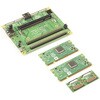
DescriptionThe Compute Module 3+ Development Kit is made for developing industrial applications with CM3+, CM3+/Lite, CM3, CM3 Lite, and CM1.The Development Kit contains the critical hardware that allows you to design the Compute Module into a custom system, and gives you the freedom to add extra components and place parts exactly where your product needs them.The kit includes the Compute Module IO(CMIO)board, which is a simple, open-source breakout board into which you can plug a Compute Module. The board hosts 120 GPIO pins, an HDMI port, a USB port, two camera ports, and two display ports.Note:A separate power supply, such as this Universal Power Supply, is required to power the product(not included in the kit).
アズワン品番67-0423-30
 Official Raspberry Pi 4 Case - Black/GraySPARKFUN
¥2,298税込¥2,528
1個
33日以内出荷
DescriptionThe official case for the Raspberry Pi 4. This case ships as two parts made of ABS plastic with access to all USB, HDMI, Audio/Video, USB and Ethernet ports. In addition, a slot on the bottom gives access to the MicroSD card. The top and bottom parts are press fit and comes in two-tone black and gray.
アズワン品番67-0426-07
 SparkFun Qwiic MultiPortSPARKFUN
¥999税込¥1,099
1個
欠品中
DescriptionQwiic is a very efficient way to quickly prototype an idea but not all Qwiic-enabled devices have two ports. The SparkFun Qwiic MultiPort adds additional ports to boards that have only one Qwiic port on the I2C bus. Once added, you can use
アズワン品番67-0420-16
 SparkFun QwiicBus - EndPointSPARKFUN
¥4,298税込¥4,728
1個
欠品中
DescriptionThe SparkFun QwiicBus EndPoint is the fastest and easiest way to extend the range of your I2C communication bus. The breakout uses NXP's PCA9615 IC, which converts the two default I2C signals into four differential signals, two for SCL and
アズワン品番67-0421-65
 SparkFun Cryptographic Co-Processor Breakout - ATECC508A QwiicSPARKFUN
¥2,698税込¥2,968
1個
欠品中
DescriptionThe SparkFun ATECC508A Cryptographic Co-Processor Breakout allows you to easily add strong authentication security to your IoT node, edge device, or embedded system. It includes two Qwiic ports for plug and play functionality. Utilizing ou
アズワン品番67-0422-83
 RFM69HCW Wireless Transceiver - COMシリーズSPARKFUN
¥2,898税込¥3,188
1個
欠品中
DescriptionThe RFM69HCW uses an SPI(Serial Peripheral Interface)to communicate with a host microcontroller, and several good Arduino libraries are available. It supports up to 256 networks of 255 nodes per network, features AES encryption to keep y
アズワン品番67-0420-86
 SparkFun Qwiic pHAT v2.0 for Raspberry PiSPARKFUN
¥2,598税込¥2,858
1個
33日以内出荷
DescriptionThe SparkFun Qwiic pHAT V2.0 for Raspberry Pi provides you with the quickest and easiest way to enter into SparkFun's Qwiic ecosystem while still using that Raspberry Pi that you've come to know and love. The Qwiic pHAT connects the I2C bus(GND, 3.3V, SDA, and SCL)on your Raspberry Pi to an array of Qwiic connectors on the HAT. Since the Qwiic system allows for daisy-chaining boards with different addresses, you can stack as many sensors as you'd like to create a tower of sensing power!The Qwiic pHAT V2.0 has four Qwiic connect ports(two on its side and two vertical), all on the same I2C bus. We've also made sure to add a simple 5V screw terminal to power boards that may need more than 3.3V and a general-purpose button(with the option to shut down the Pi with a script). Also updated, the mounting holes found on the board are now spaced to accommodate the typical Qwiic board dimension of 1.0"×1.0". This HAT is compatible with any Raspberry Pi that utilizes the standard 2x20 GPIO header as well as the NVIDIA Jetson Nano and Google Coral.NoteWhen placing a Raspberry Pi and the pHAT in an enclosure(like the Pi Tin), we noticed that the pHAT was not fully inserted in Pi's header pins. For a secure connection, you'll need to add a pair of 1x20 stackable headers to extend the pins to your cart.The SparkFun Qwiic Connect System is an ecosystem of I2C sensors, actuators, shields and cables that make prototyping faster and less prone to error. All Qwiic-enabled boards use a common 1mm pitch, 4-pin JST connector. This reduces the amount of required PCB space, and polarized connections mean you can't hook it up wrong.Get Started with the SparkFun Qwiic pHAT GuideFeatures4x Qwiic Connection Ports1x 5V Tolerant Screw Terminal1x General Purpose ButtonHAT-compatible 40-pin Female Header
アズワン品番67-0422-97
 SparkFun AST-CAN485 Dev BoardSPARKFUN
¥19,980税込¥21,978
1個
欠品中
DescriptionThe SparkFun AST-CAN485 Dev Board is a miniature Arduino in the compact form factor of the Pro Mini. In addition to all the usual features that a mini Arduino has, it possesses an onboard CAN(Control Area Network)and RS485 ports, enabling q
アズワン品番67-0422-53
 SparkFun MicroMod Qwiic Carrier Board - DoubleSPARKFUN
¥4,298税込¥4,728
1個
33日以内出荷
DescriptionThe MicroMod Qwiic Carrier Board can be used to rapidly prototype with other Qwiic devices. The MicroMod M.2 socket provides users the freedom to experiment with any processor board in the MicroMod ecosystem. This board also features two Qwiic connectors and eight 4-40 screw inserts to connect and mount Qwiic devices.This version of the SparkFun MicroMod Qwiic Carrier Board features two ports for our standard 1in. by 1in. Qwiic breakouts. However, you aren't beholden to attaching just a duo of Qwiic breakouts since you are able to stack the boards on top of each other, allowing you to hook up a full circuit of Qwiic sensors and accessories to fully utilize your next project!MicroMod is a modular interface ecosystem that connects a microcontroller "processor board" to various "carrier board" peripherals. Utilizing the M.2 standard, the MicroMod standard is designed to easily swap out processors on the fly. Pair a specialized carrier board for the project you need with your choice of compatible processor!Get Started With the MicroMod Qwiic Carrier Board GuideFeaturesM.2 MicroMod(Processor Board)ConnectorUSB-C Connector3.3V 1A Voltage RegulatorQwiic ConnectorsBoot/Reset ButtonsCharge CircuitEight 4-40 Inserts
アズワン品番67-0423-51
 USB Female Type B ConnectorSPARKFUN
¥479税込¥527
1個
33日以内出荷
USB Type 'B' Female connector. The 4 connection pins have .1" spacing allowing it to be inserted into development boards and perf boards with mild modification. You can either drill two 80mil holes for the support posts、or cut them off completely.
アズワン品番67-0454-07
 SparkFun XBee Explorer DongleSPARKFUN
¥10,980税込¥12,078
1個
33日以内出荷
DescriptionThis is the SparkFun XBee Explorer Dongle unit for the Digi XBee module line. With the XBee Explorer Dongle you can plug the unit directly into your USB port and have it act as a gateway between your computer and the XBee. No cables needed
仕様●項目1:USBドングル●項目2:無線ネットワーク、データー通信●項目4:XBee●項目7:XBeeアズワン品番67-0455-61
 SparkFun Thing Plus - RP2040SPARKFUN
¥6,698税込¥7,368
1個
33日以内出荷
DescriptionThe SparkFun Thing Plus - RP2040 is a low-cost, high performance board with flexible digital interfaces featuring the Raspberry Pi Foundation's RP2040 microcontroller. Besides the Thing Plus orFeatherfootprint(with 18 GPIO pins), the board also includes an SD card slot, 16MB(128Mbit)flash memory, a JST single cell battery connector(with a charging circuit and fuel gauge sensor), an addressable WS2812 RGB LED, JTAG PTH pins, four(4-40 screw)mounting holes, and our signature Qwiic connector.The RP2040 contains two ARM Cortex-M0+ processors(up to 133MHz)and features:264kB of embedded SRAM in six banks6 dedicated IO for SPI Flash(supporting XIP)30 multifunction GPIO:Dedicated hardware for commonly used peripheralsProgrammable IO for extended peripheral supportFour 12-bit ADC channels with internal temperature sensor(up to 0.5 MSa/s)USB 1.1 Host/Device functionalityThe RP2040 is supported with both C/C++ and MicroPython cross-platform development environments, including easy access to runtime debugging. It has UF2 boot and floating-point routines baked into the chip. While the chip has a large amount of internal RAM, the board includes an additional 16MB of external QSPI flash memory to store program code.The SparkFun Qwiic Connect System is an ecosystem of I2C sensors, actuators, shields and cables that make prototyping faster and less prone to error. All Qwiic-enabled boards use a common 1mm pitch, 4-pin JST connector. This reduces the amount of required PCB space, and polarized connections mean you can't hook it up wrong.Get Started With the Thing Plus RP2040 Hookup GuideFeaturesSparkFun Thing Plus - RP2040 FeaturesRaspberry Pi Foundation's RP2040 microcontroller16MB QSPI Flash MemoryJTAG PTH PinsThing Plus(or Feather)Form-Factor:18[1]x Multifunctional GPIO Pins[2]Four available 12-bit ADC channels with internal temperature sensor(500kSa/s)Up to eight 2-channel PWMUp to two UARTsUp to two I2C busesUp to two SPI busesUSB-C Connector:USB 1.1 Host/Device functionality2-pin JST Connector for a LiPo Battery(not included)500mA charging circuitQwiic ConnectorButtons:BootResetLEDs:PWR- Red 3.3V power indicatorCHG- Yellow battery charging indicator25- Blue status/test LED(GPIO 25)WS2812- Addressable RGB LED(GPIO 08)Four Mounting Holes:4-40 screw compatibleDimensions:2.3"×0.9"RP2040 General FeaturesDual Cortex M0+ processors, up to 133 MHz264 kB of embedded SRAM in 6 banks6 dedicated IO for QSPI flash, supporting execute in place(XIP)30 programmable IO for extended peripheral supportSWD interfaceTimer with 4 alarmsReal time counter(RTC)USB 1.1 Host/Device functionalitySupported programming languagesMicroPythonC/C++1.Note:GPIO 08is not included in this count, as it passes through the WS2812 addressable RGB LED first.GPIO 07andGPIO 23are counted as a single GPIO because they are tied together.2.Note:The GPIO pins are programmable so you can reconfigure the pins! Check out the RP2040 datasheet for more information on the GPIO functionality.
アズワン品番67-0423-56
 SparkFun RFM69 Breakout 434MHzSPARKFUN
¥4,398税込¥4,838
1個
33日以内出荷
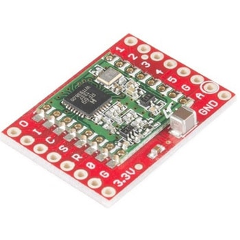
DescriptionThis is the SparkFun RFM69 Breakout, a small piece of tech that breaks out all the pins available on the RFM69HCW module as well as making the transceiver easy to use. The RFM69HCW is an inexpensive and versatile radio module that operates in the unlicensed ISM(Industry, Science and Medicine)radio band. It's perfect for building inexpensive short-range wireless networks of sensors and actuators for home automation, citizen science and more.This RFM69HCW operates on the 434MHz frequency and is capable of transmitting at up to 100mW and up to 300kbps, but you can change both of those values to fit your application. For example, you can maximize range by increasing the transmit power and reducing the data rate, or you can reduce both for short-range sensor networks that sip battery power. At full power and with simple wire antennas, we can get messages from one side of a large office building to the other through numerous internal walls. In open air you can reach 500 meters or more. With more complex antennas and modulation schemes, similar parts have successfully transmitted from space to the ground(by very smart amateur radio enthusiasts; your mileage may vary)!The RFM69HCW uses an SPI(Serial Peripheral Interface)to communicate with a host microcontroller, and several good Arduino libraries are available. It supports up to 256 networks of 255 nodes per network, features AES encryption to keep your data private, and transmits data packets up to 66 bytes long.SparkFun sells two versions of the RFM69HCW:a 915MHz version and this 434MHz version. Although the ISM band is license-free, the band itself is different in different areas. Very roughly, 915MHz is for use in the Americas, and the 434MHz version is for use in Europe, Asia and Africa. Check your local regulations for other areas.Get Started with the RFM69HCW Hookup GuideFeaturesTransmit power:-18dBm(0.016mW)to +20dBm(100mW)in 1dBm stepsReceive sensitivity:down to -120dBm at 1.2kbpsModulation types:FSK GFSK MSK GMSK OOKBit rates(FSK):1.2kbps to 300kbpsVoltage range:1.8V to 3.6VCurrent consumption:0.1uA sleep, 1.25mA standby, 16mA receive, 130mA transmit(max)Encryption:AES 128-bit(optional)Packet buffer(FIFO):66 bytes0.8"×1.1"
アズワン品番67-0429-33
 Panel Mount USB-C Extension Cable - 6"SPARKFUN
¥5,598税込¥6,158
1個
欠品中
DescriptionThis panel mount USB-C extension cable enables you to more easily enclose a project that contains a USB-C port. The cable is 6" in length and includes two 14mm M3 screws compatible with the cable's 3mm panel mount holes, spaced 18mm apart.
アズワン品番67-0420-56
 Panel Mount USB-B to Micro-B Cable - 6"SPARKFUN
¥1,198税込¥1,318
1個
欠品中
DescriptionThis panel mount USB-B(female)to micro-B(male)cable enables you to more easily enclose a project that contains a USB micro-B port. The cable is 6" in length and includes two 14mm M3 screws compatible with the cable's 3mm panel mount holes, spaced 28.5mm apart.
アズワン品番67-0420-57
 Panel Mount USB Micro-B Extension Cable - 6"SPARKFUN
¥1,398税込¥1,538
1個
欠品中
DescriptionThis panel mount USB micro-B extension cable enables you to more easily enclose a project that contains a USB micro-B port. The cable is 6" in length and includes two 14mm M3 screws compatible with the cable's 3mm panel mount holes, spaced 16.5mm apart.
アズワン品番67-0420-58
 RFM69HCW Wireless Transceiver - COMシリーズSPARKFUN
¥2,798税込¥3,078
1個
欠品中
DescriptionThe RFM69HCW uses an SPI(Serial Peripheral Interface)to communicate with a host microcontroller, and several good Arduino libraries are available. It supports up to 256 networks of 255 nodes per network, features AES encryption to keep your data private, and transmits data packets up to 66 bytes long.Features+20 dBm - 100 mW Power Output CapabilityHigh Sensitivity:down to -120 dBm at 1.2 kbpsHigh Selectivity:16-tap FIR Channel FilterBullet-proof front end:IIP3 = -18 dBm, IIP2 = +35 dBm,80 dB Blocking Immunity, no Image Frequency responseLow current:Rx = 16 mA, 100nA register retentionProgrammable Pout:-18 to +20 dBm in 1dB stepsConstant RF performance over voltage range of moduleFSK Bit rates up to 300 kb/sFully integrated synthesizer with a resolution of 61 HzFSK, GFSK, MSK, GMSK and OOK modulationsBuilt-in Bit Synchronizer performing Clock RecoveryIncoming Sync Word Recognition115 dB+ Dynamic Range RSSIAutomatic RF Sense with ultra-fast AFCPacket engine with CRC-16, AES-128, 66-byte FIFOBuilt-in temperature sensor
アズワン品番67-0420-85
 SparkFun Line Follower ArraySPARKFUN
¥13,980税込¥15,378
1個
欠品中
DescriptionThe SparkFun Line Follower Array is a long board consisting of eight IR sensors that have been configured to read as digital bits! We have designed the SparkFun Line Follower Arrays to follow a dark line of about 3/4 inch width or smaller(spray paint or electrical tape)on a light background. Each array features visible LEDs that point upward when the board is attached(properly)so you can see what the robot sees, brightness control right on the board, and an I2C interface for reading and power control. Here at SparkFun, the RedBot Shadow Chassis was used as a test platform but really this was designed as an add-on for almost any bot.The line follower functions by taking an 8-bit reading of reflectance for use with following lines or reading dark/light patterns and can see from about 1/4 to 3/4 inches away. The IR brightness control and indicator can be adjusted with the on-board potentiometer and is capable of showing you the strength of the IR LEDs. Illumination can be turned on and off with software to conserve power, or left on all the time for faster readings. The SparkFun Line Follower Array requires 5V of power with a supply current range of 25-185mA with strobing disabled and 16-160mA with it enabled. Additionally we have added six mounting holes to the line follower with the two inner holes designed to fit our Shadow Chassis while the other four are general purpose.Note:As you know our Sun emits quite a bit of infrared light, making the SparkFun Line Follower Array much less effective in direct sunlight. Plan your projects accordingly!Features8 sensor eyes(QRE1113, like in our line sensor breakout)I2C interfaceAdjust IR brightness on the fly with a knobSwitch IR on and off with softwareSwitch visual indicators on and off with softwareInvert dark/light sight with softwareBased on the SX1509 I/O expander
アズワン品番67-0426-55
 SparkFun RTK SurveyorSPARKFUN
¥129,800税込¥142,780
1個
33日以内出荷
DescriptionThe SparkFun RTK Surveyor is an easy to use GNSS receiver for centimeter-level positioning. Perfect for surveying, this preprogrammed device can also be used for autonomous driving, navigation, asset tracking and any other application where there is a clear view of the sky. The RTK Surveyor can also be used as a base station. With the flick of a switch, two RTK Surveyors can be used to create an RTK system capable of 14mm horizontal positional accuracy. The built-in Bluetooth(R)connection via an ESP32 WROOM enables the user to use the RTK Surveyor with their choice of GIS application on a phone or tablet. The built in battery allows field use for up to four hours and is compatible with common USB battery banks.This device can be used in four modes:GNSS Positioning(~30cm accuracy)GNSS Positioning with RTK(1.4cm accuracy)GNSS Base StationGNSS Base Station NTRIP ServerIn Position mode the device receives L1/L2 signals from a user-provided antenna and the high-grade GNSS receiver provides lat/long and altitude with accuracies around 300mm.In Positioning with RTK mode the device receives L1/L2 signals from the antenna and correction data from a base station. The correction data can be obtained from a cellular link to online correction sources or over a radio link to a 2nd RTK Surveyor setup as a base station.In Base Station mode the device is mounted to a temporary position(like a tripod)and begins transmitting correction data over a radio or internet connection. A base is often used in conjunction with a second unit set to 'Positioning with RTK' to obtain the 14mm relative accuracy.In Base Station NTRIP Server mode the device is mounted to a semi or permanently fixed position(like a roof)and connects over WiFi to transmit the correction data to a NTRIP caster so that any rover can access the correction data over a cellular or internet connection. This type of base is a very easy way to setup a very precise absolute correction source.Two cables are provided with the RTK Surveyor allowing a user to plug on our easy to use Serial Telemetry Radios or their own radio link. If a local correction source is within 10km, a user can also use their phone to provide correction data over the Bluetooth(R)link(no external radio needed!).Note:The SparkFun RTK Surveyor is just the enclosed device and does NOT include an antenna, serial telemetry radio, or associated mounting pieces. These items will need to be purchased separately from the Hookup Accessories below.Get Started With the SparkFun RTK Surveyor GuideFeaturesGNSS Receiver:ZED-F9PConcurrent reception of GPS, GLONASS, Galileo and BeiDouReceives both L1C/A and L2C bandsCurrent:68mA - 130mA(varies with constellations and tracking state)Time to First Fix:25s(cold), 2s(hot)Max Navigation Rate:PVT(basic location over UBX binary protocol)- 25HzRTK - 20HzRaw - 25HzHorizontal Position Accuracy:2.5m without RTK0.010m with RTKMax Altitude:50km(31 miles)Max Velocity:500m/s(1118mph)Bluetooth(R)Transceiver:ESP32 WROOMXtensa(R)dual-core 32-bit LX6 microprocessorUp to 240MHz clock frequency16MB of flash storage520kB internal SRAMIntegrated 802.11 BGN WiFi transceiverIntegrated dual-mode Bluetooth(R)(classic and BLE)Hardware accelerated encryption(AES, SHA2, ECC, RSA-4096)2.5 μA deep sleep currentOverall DeviceInternal Battery:LiPo 1000mAh with 500mA chargingRadio Port:3.3V TTL Serial(57600bps RTCM TX/RX)Data Port:3.3V TTL Serial(115200bps NMEA)Weight:132g(entire device including battery)Dimensions:118mm×79mm×30mm(4.7in×3.1in×1.2in)1x Qwiic Connector1x microSD Socket for optional loggingChanges:This version(which replaces SPX-17369)uses a reinforced edge mount SMA connector for better resiliency when a fixed 'stub' antenna is used.
アズワン品番67-0423-95
 SparkFun Qwiic AdapterSPARKFUN
¥479税込¥527
1個
33日以内出荷
DescriptionThe SparkFun Qwiic Adapter provides the perfect means to make any old I2C board into a Qwiic-enabled board. This adapter breaks out the I2C pins from the Qwiic connectors to pins that you can easily solder with your favorite I2C-enabled device.The Qwiic Adapter has two Qwiic connection ports, all on the same I2C bus. Four plated through holes are broken out for SCL, SDA, 3.3V and GND. These pins can be used to convert an old I2C-enabled device into a Qwiic-enabled board.The SparkFun Qwiic Connect System is an ecosystem of I2C sensors, actuators, shields and cables that make prototyping faster and less prone to error. All Qwiic-enabled boards use a common 1mm pitch, 4-pin JST connector. This reduces the amount of required PCB space, and polarized connections mean you can't hook it up wrong.Get Started with the SparkFun Qwiic Adapter GuideFeatures2x Qwiic Connection PortsBroken-out I2C Pins
アズワン品番67-0419-69
 SparkFun Breadboard Power Supply 5V/3.3VSPARKFUN
¥3,998税込¥4,398
1個
33日以内出荷
Here is a very simple breadboard power supply kit that takes power from a DC wall wart and outputs a selectable 5V or 3.3V regulated voltage. The .1" headers are mounted on the bottom of the PCB for simple insertion into a breadboard. Pins labeled VCC and GND plug directly into the power lines. The lone pair of pins have no electrical connection but help support the PCB.There are two pins available within the barrel jack footprint. Any stripped +/- DC supply can be connected instead of the barrel connector. Board has both an On/Off switch and a voltage select switch(3.3V/5V).Comes as a bag of parts kit and is easily assembled if you can follow the silkscreen indicators and have beginning experience with a soldering iron. You will need to read the resistor bands or use a multimeter to determine the resistor sizes.Dimensions:1.25x1.25"Kit Includes:DC Barrel Connector(2.1mm center positive)TO-220 Voltage Regulator(LM317 1.5A max current)1N4004 Reverse Protection Diode100uF 25V Capacitor10uF 25V Capacitor0.1uF 50V CapacitorRed Power LED - High Brightness2×SPDT Slide Switch4×0.1" Header Pins2×330 Resistor 1/6W390 Resistor 1/6W240 Resistor 1/6WBare PCB with Silkscreen IndicatorsPTC resettable fuse
仕様●項目1:組込み(組立てキット)●項目2:電源●項目4:リニア電源●項目8:ブレッドボード用電源アズワン品番67-0454-01
 モータードライバSPARKFUN
¥4,798税込¥5,278
1個
33日以内出荷
DescriptionThe TB6612FNG Motor Driver can control up to two DC motors at a constant current of 1.2A(3.2A peak). Two input signals(IN1 and IN2)can be used to control the motor in one of four function modes:CW, CCW, short-brake and stop. The two motor outputs(A and B)can be separately controlled, and the speed of each motor is controlled via a PWM input signal with a frequency up to 100kHz. The STBY pin should be pulled high to take the motor out of standby mode.Logic supply voltage(VCC)can be in the range of 2.7--5.5VDC, while the motor supply(VM)is limited to a maximum voltage of 15VDC. The output current is rated up to 1.2A per channel(or up to 3.2A for a short, single pulse).This little board comes with all components installed as shown. Decoupling capacitors are included on both supply lines. All pins of the TB6612FNG are broken out to two 0.1" pitch headers; the pins are arranged such that input pins are on one side and output pins are on the other.Note:If you are looking for the SparkFun Motor Driver with headers, it can be found here or in theSimilar Productsbelow.Get Started With the Motor Driver Hookup GuideFeaturesPower supply voltage:VM = 15V max, VCC = 2.7--5.5VOutput current:Iout = 1.2A(average)/ 3.2A(peak)Standby control to save powerCW/CCW/short-brake/stop motor control modesBuilt-in thermal shutdown circuit and low-voltage detecting circuitAll pins of the TB6612FNG broken out to 0.1" spaced pinsFiltering capacitors on both supply lines
アズワン品番67-0395-99
 SparkFun LTE CAT M1/NB-IoT Shield - SARA-R4SPARKFUN
¥29,980税込¥32,978
1個
33日以内出荷
DescriptionThe SparkFun LTE CAT M1/NB-IoT Shield equips your Arduino or Arduino-compatible microcontroller with access to data networks across the globe. This shield adds wireless, high-bandwidth cellular functionality to your IoT project while maintaining low power consumption and small footprint. The SparkFun LTE CAT M1/NB-IoT Shield is based off the Arduino R3's footprint that allows you to easily incorporate it with favorite Arduino-based device.At the heart of the LTE Cat M1/NB-IoT shield is u-blox SARA-R410M-02B LTE Cat M1/NB-IoT modem. Cat M1(Category M1)and NB-IoT(Narrowband IoT)are both Low Power Wide Area Network(LPWAN)technologies that are designed to provide cellular communication to small IoT devices. They operate on LTE network bands just like most smartphones, and should be supported by most cellular network carriers. The u-blox SARA-R4 module communicates over UART via simple AT command set. We've provided library to help you get started with everything from sending SMS text messages to communicating with servers over TCP/IP connection. Additionally, both the module and library support an I2C GPS interface via Qwiic connector, so you can plug in u-blox GPS module and start remotely tracking your project.Each SparkFun LTE CAT M1/NB-IoT Shield also includes ceramic, Molex 1462000001 SMD antenna. The antenna has gain of 3.8dBi around 1.7GHz to 2.7GHz. However, if you would prefer to use an external antenna, we have provided U.FL connector that can be utilized by simply slicing through jumper with hobby knife.Please be aware that there are few extra parts required to get this shield fully functioning, other than an Arduino-based device. First, you'll need to supply your own SIM card, such as this one from Hologram(we do also offer this shield with an included one as well)and your own headers which will need to be soldered on.Note:Be sure to check theHardware Overviewsection in the Hookup Guide for compatible GPS modules. The onboard Qwiic connector is only designed to support u-blox-based GPS modules. It does not support any other GPS modules or sensors. We are continuing to add more modules so be sure to check back every so often to find out more!Need custom board?This component can be found in SparkFun's La Carte board builder. You can have custom design fabricated with this component and your choice of hundreds of other sensors, actuators and wireless devices delivered to you in just few weeks.Get Started with the SparkFun LTE CAT M1/NB-IoT Shield GuideDocumentsSchematicEagle FilesHookup GuideDatasheetsSARA-R4Ceramic AntennaSARA-R4 AT Command SetArduino LibraryGitHub
アズワン品番67-0420-75
 SparkFun micro:climate kit for micro:bit - v3.0SPARKFUN
¥37,980税込¥41,778
1個
33日以内出荷
DescriptionThe SparkFun micro:climate kit is a full weather station kit that is built on top of the weather:bit carrier board. Unlike previous weather kits we've carried, this micro:climate kit is Qwiic enabled and includes our tried-and-true Weather Meters and Soil Moisture Sensor, so whether you're an agriculturalist, a professional meteorologist or a hobbyist, you will be able to build a high-grade weather station powered by the micro:bit. You can even talk via wireless communication between two micro:bits with this kit to be able to monitor the weather without being exposed to it!Inside each micro:climate kit you will find all the components required to build your micro:bit into a go-to weather sensor; the only parts not included are two AAA batteries, microSD card, and the micro:bit itself. Simply add your own micro:bit to the provided weather:bit, assemble the kit, and you will be ready to start sensing. The SparkFun micro:climate kit is a great way to get your feet wet in high-grade sensors --- just not literally; that's the weather:bit's job!The kit does not require any soldering and is recommended for anyone curious about weather-sensing technology or the micro:bit platform.The micro:bit is a pocket-sized computer that lets you get creative with digital technology. Between the micro:bit and our shield-like bit boards you can do almost anything while coding, customizing and controlling your micro:bit from almost anywhere! You can use your micro:bit for all sorts of unique creations, from robots to musical instruments and more. At half the size of a credit card, this versatile board has vast potential!Note:The SparkFun micro:climate kit doesNOTinclude a micro:bit board. The micro:bit board will need to be purchased separately. You will also need a microSD card when logging data and AAA batteries to power remotely.Get started with the micro:climate kit Guide
アズワン品番67-0424-40
 I/O Expander - MCP23008SPARKFUN
¥639税込¥703
1個
33日以内出荷
DescriptionAdd another eight pins to your microcontroller using a MCP23008 port expander. The MCP23008 uses two I2C pins which can be shared with other I2C devices, and in exchange gives you eight general purpose pins. You can set each of eight pins to be input, output, or input with a pullup. There's even the ability to get an interrupt via an external pin when any of the inputs change so you don't have to keep polling the chip.Use this chip from 2.7-5.5V(good for any 3.3V or 5V setup), and you can sink/source up to 20mA from any of the I/O pins so this will work for LEDs and such. Team it up with a high-power MOSFET if you need more juice. DIP package means it will plug into any breadboard or perfboard.You can set the I2C address by tying the ADDR0-2 pins to power or ground, for up to eight unique addresses. That means eight chips can share a single I2C bus - that's 64 I/O pins!Features8-bit remote bidirectional I/O portHigh-speed I2C interface(MCP23008)Hardware address pinsConfigurable interrupt output pinConfigurable interrupt sourcePolarity Inversion register for input port data polarity config.External reset inputLow standby current:1 μA(max.)・ Operating voltage:1.8V to 5.5V @ -40℃ to +85℃ I2C @ 100 kHz SPI @ 5 MHz2.7V to 5.5V @ -40℃ to +85℃ I2C @ 400 kHz SPI @ 10 MHz4.5V to 5.5V @ -40℃ to +125℃ I2C @ 1.7 kHz SPI @ 10 MHz
アズワン品番67-0421-32
 SparkFun MicroMod Qwiic Carrier Board - SingleSPARKFUN
¥3,500税込¥3,850
1個
33日以内出荷
DescriptionThe MicroMod Qwiic Carrier Board can be used to rapidly prototype with other Qwiic devices. The MicroMod M.2 socket provides users the freedom to experiment with any processor board in the MicroMod ecosystem. This board also features two Qwiic connectors and four 4-40 screw inserts to connect and mount Qwiic devices.This version of the SparkFun MicroMod Qwiic Carrier Board features a single port for our standard 1in. by 1in. Qwiic Breakouts. However, you aren't beholden to attaching just one Qwiic breakout since you are able to stack the boards on top of each other, allowing you to hook up a full circuit of Qwiic sensors and accessories to fully utilize your next project!MicroMod is a modular interface ecosystem that connects a microcontroller "processor board" to various "carrier board" peripherals. Utilizing the M.2 standard, the MicroMod standard is designed to easily swap out processors on the fly. Pair a specialized carrier board for the project you need with your choice of compatible processor!Get Started With the MicroMod Qwiic Carrier Board GuideFeaturesM.2 MicroMod(Processor Board)ConnectorUSB-C Connector3.3V 1A Voltage RegulatorQwiic ConnectorsBoot/Reset ButtonsCharge CircuitFour 4-40 Inserts
アズワン品番67-0423-50
 SparkFun Cryptographic Co-Processor Breakout - ATECC608A QwiicSPARKFUN
¥1,498税込¥1,648
1個
33日以内出荷
DescriptionProduct Restrictions:To access certain features of the ATECC608A, users will need to contact Microchip and sign an NDA contract to obtain the complete datasheet. Due to the required NDA - technical support, an Arduino library, and hookup guide are not provided for users on this product.The SparkFun ATECC608A Cryptographic Co-processor Breakout allows you to add strong security to your IoT node, edge device, or embedded system. This includesasymmetricauthentication,symmetricAES-128 encryption/decryption, and much more. As stated above, the ATECC608A has limited Arduino support and the complete datasheet is under NDA with Microchip.This breakout board includes two Qwiic ports for plug and play functionality. Utilizing our handy Qwiic system, no soldering is required to connect it to the rest of your system. However, we still have broken out 0.1"-spaced pins in case you prefer to use a breadboard. The ATECC608A chip is capable of many cryptographic processes, including, but not limited to:Creating and securely storing unique asymmetric key pairs based on Elliptic Curve Cryptography(FIPS186-3).AES-128:Encrypt/Decrypt, Galois Field Multiply for GCMCreating and verifying 64-byte digital signatures(from 32-bytes of message data).Creating a shared secret key on a public channel via Elliptic Curve Diffie-Hellman Algorithm.SHA-256 HMAC Hash including off-chip context save/restoreInternal high quality FIPS random number generator.Embedded in the chip is a 10Kb EEPROM array that can be used for storing keys, certificates, data, consumption logging, and security configurations. Access to the sections of memory can then be restricted and the configuration locked to prevent changes. Each ATECC608A Breakout ships with a guaranteed unique 72-bit serial number and includes several security features to prevent physical attacks on the device itself, or logical attacks on the data transmitted between the device.A summary datasheet for the ATECC608A is available here. The full datasheet is under NDA with Microchip. You will need to contact them for access to the entire datasheet. Meanwhile, the ArduinoATECCX08 Library currently only supports the ATECC608A with SAMD21 Arduino boards.We do have much more support for the ATECC508A version of this chip. Please check out our ATECC508A Hookup Guide and Arduino Library(which includes six examples). This will get you familiar with the basics of elliptic curve cryptography and signing/verifying data with the ATECC508A version of the chip.Note:The I2C address of the ATECC608A is 0x60 and is software-configurable to any address. A multiplexer/Mux is required to communicate to multiple ATECC608A sensors at the default address when on a single bus. If you need to use more than one ATECC608A sensor at the default address, consider using the Qwiic Mux Breakout.Note:The ATECC608A can be only configured once before it isPERMANENTLYlocked. It is advisable that users purchase multiple boards in order to use other configurations and explore the advanced functions of the ATECC608A.Additionally, this boardIScapable of encrypting and decrypting data. However, to access these additional features, you will need to contact Microchip and sign an NDA contract to obtain the complete datasheet.It is recommended that an SparkFun RedBoard Turbo - SAMD21 Development Board is used with this product due to the buffer size required on the I2C bus.The SparkFun Qwiic Connect System is an ecosystem of I2C sensors, actuators, shields and cables that make prototyping faster and less prone to error. All Qwiic-enabled boards use a common 1mm pitch, 4-pin JST connector. This reduces the amount of required PCB space, and polarized connections mean you can't hook it up wrong.FeaturesOperating Voltage:2.0V-5.5V(Default on Qwiic System:3.3V)Active Current Draw(for ATECC608A):16 mASleep Current(for ATECC608A):<150 nAGuaranteed Unique 72-bit Serial Number10 Kb EEPROM Memory for Keys, Certificates, and DataStorage for up to 16 Keys256-bit Key LengthInternal High-Quality FIPS Random Number Generator(RNG)Configurable I2C Address(7-bit):0x60(Default)
アズワン品番67-0423-59
 LilyPad ProtoSnap PlusSPARKFUN
¥14,980税込¥16,478
1個
33日以内出荷
DescriptionThe LilyPad ProtoSnap Plus is a sewable electronics prototyping board that you can use to explore circuits and programming, then break apart to make an interactive fabric or wearable project. Programming the ProtoSnap Plus is easy with the free Arduino software you'll need to program the ATmega32U4 on LilyPad USB Plus at the heart of the board. Once you've installed the software, you'll be able to write and upload your own programs to the board, making it do almost anything you want.At the center of the ProtoSnap Plus is the LilyPad USB Plus microcontroller, pre-wired to a LilyPad board including a LilyPad Light Sensor, LilyPad Buzzer, LilyPad Button Board, four pairs of colored LilyPad LEDs and a LilyPad Slide Switch. Because these components are connected together on the ProtoSnap board, you can test out your project ideas before you sew. The ProtoSnap Plus also includes expansion ports that let you sew your wearables together or use alligator cables to easily connect external sensors and components. After testing out your coding ideas using the attached LilyPad pieces, you can break apart the prototyping board and sew them into your project!Please be aware that the Lilypad ProtoSnap Plus isNOT supported on Windows 7/8due to a lack of support drivers for those specific OS's.Note:A portion of this sale is given back to Dr. Leah Buechley for continued development and education in e-textiles.Get Started with the LilyPad ProtoSnap Plus Guide
アズワン品番67-0422-45
 SparkFun MicroMod ATP Carrier BoardSPARKFUN
¥6,298税込¥6,928
1個
33日以内出荷
DescriptionAccess all the pins(i.e. ATP)of the MicroMod Processor Boards with the SparkFun MicroMod ATP Carrier Board! This board breaks out the MicroMod Processor Board's pins on the M.2 connector to 0.1" spaced female headers and PTH pads on the edge of the board. This Carrier Board is great if you're interested in testing out different MicroMod Processor Boards for your application.A modern USB-C connector makes programming easy. In addition to the pins broken out, two separate Qwiic-enabled I2C ports allow you to easily daisy chain Qwiic-enabled devices. We've exposed the SWD pins for more advanced users who prefer to use the power and speed of professional tools. A USB-A connector is provided for Processor Boards that have USB Host support. A backup battery is provided for processor boards with RTC. If you need a "lot" of GPIO with a simple-to-program, ready for market module, the ATP is the fix you need. We've even added a convenient jumper to measure the current consumption for low power testing.MicroMod is a modular interface ecosystem that connects a microcontroller "processor board" to various "carrier board" peripherals. Utilizing the M.2 standard, the MicroMod standard is designed to easily swap out processors on the fly. Pair a specialized carrier board for the project you need with your choice of compatible processor!Get Started with the MicroMod ATP Carrier Board GuideFeaturesM.2 ConnectorOperating Voltage Range~3.3V to 6.0V(via VIN to AP7361C 3.3V Voltage Regulator)3.3V(via 3V3)Ports [1]1x USB type C1x USB type A Host2x Qwiic Enabled I2C1x CAN1x I2S2x SPI2x UARTs2x Dedicated Analog Pins2x Dedicated PWM Pins2x Dedicated Digital Pins12x General Purpose Input Output Pins1x SWD 2x5 header1mAh battery backup for RTCButtonsResetBootLEDsPower3.3VPhillips #0 M2.5x3mm screw included[1] Note:Depending on the design of the Processor Board, not all the pins may be accessible.
アズワン品番67-0423-18
 SparkFun moto:bit - micro:bit Carrier Board QwiicSPARKFUN
¥9,398税込¥10,338
1個
33日以内出荷
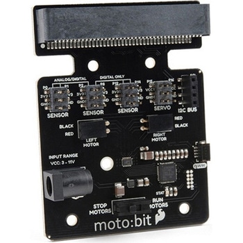
DescriptionThe SparkFun moto:bit is a fully loaded "carrier" board for the micro:bit that, when combined with the micro:bit, provides you with a fully functional robotics platform. The moto:bit offers a simple, beginner-friendly robotics controller capable of operating a basic robotics chassis. Onboard each moto:bit are multiple I/O pins, as well as a vertical Qwiic connector, capable of hooking up servos, sensors and other circuits. At the flip of the switch you can get your micro:bit moving!The moto:bit connects to the micro:bit via an updated SMD, edge connector at the top of the board, making setup easy. This creates a handy way to swap out micro:bits for programming, while still providing reliable connections to all of the different pins on the micro:bit. We have also included a basic barrel jack on the moto:bit that is capable of providing power to anything you connect to the carrier board.The micro:bit is a pocket-sized computer that lets you get creative with digital technology. Between the micro:bit and our shield-like bit boards you can do almost anything while coding, customizing and controlling your micro:bit from almost anywhere! You can use your micro:bit for all sorts of unique creations, from robots to musical instruments and more. At half the size of a credit card, this versatile board has vast potential!Note:The SparkFun moto:bit doesNOTinclude a micro:bit board. The micro:bit will need to be purchased separately.Get started with the moto:bit GuideFeaturesMore reliable Edge connector for easy use with the micro:bitFull H-Bridge for control of two motorsControl servo motorsVertical Qwiic ConnectorI2C port for extending functionalityPower and battery management onboard for the micro:bit
アズワン品番67-0422-89
 SparkFun Real Time Clock Module - RV-1805 QwiicSPARKFUN
¥7,798税込¥8,578
1個
33日以内出荷
DescriptionGet with the times, already! This SparkFun Real Time Clock(RTC)Module is a Qwiic-enabled breakout board for the RV-1805 chipset. The RTC is ultra-low power(running at only about 22nA in its lowest power setting)so it can use a supercapacitor for backup power instead of a normal battery. This means you get plenty of charge and discharge cycles without any degradation to the "battery." To make it even easier to get your readings, all communication is enacted exclusively via I2C, utilizing our handy Qwiic system so no soldering is required to connect it to the rest of your system. However, we still have broken out 0.1"-spaced pins in case you prefer to use a breadboard.This RTC module's built in RV-1805 has not one, but two internal oscillators:a 32.768kHz tuning fork crystal and a low power RC based oscillator and can automatically switch between the two using the more precise crystal to correct the RC oscillator every few minutes. This feature allows the module to maintain a very accurate date and time with the worst case being +/- about three minutes over a year. The RV-1805 also has a built in trickle charger so as soon as the RTC is connected to power the it will be fully charged in under 10 minutes and has the ability to switch power to other systems allowing it to directly turn on or off a power hungry device such as a microcontroller or RF engine.There is also the option to add a battery to the board if the supercapacitor just isn't going keep your project powered long enough(keep in mind, the supercap can hypothetically make the board keep time for around 35 days), you can solder on an external battery. That means you can let board sit with no power or connection to the outside world and the current hour/minute/second/date will be maintained.Note:The I2C address of the RV-1805 is 0x69 and is hardware defined. A multiplexer/Mux is required to communicate to multiple RV-1805 sensors on a single bus. If you need to use more than one RV-1805 sensor consider using the Qwiic Mux Breakout.The SparkFun Qwiic connect system is an ecosystem of I2C sensors, actuators, shields and cables that make prototyping faster and less prone to error. All Qwiic-enabled boards use a common 1mm pitch, 4-pin JST connector. This reduces the amount of required PCB space, and polarized connections mean you can't hook it up wrong.Get Started with the RV-1805 Real Time Clock Module GuideFeaturesOperating Voltage(Startup):1.6V - 3.6VOperating Voltage(Timekeeping):1.5V - 3.6VOperating Temperature:-40℃ - 85℃Time Accuracy:±2.0 ppmCurrent Consumption:22nA(Typ.)I2C Address:0xD2Supercapacitor for Backup Power2x Internal Oscillators2x Qwiic Connectors
アズワン品番67-0420-02
 PureThermal Mini Pro JST-SR with FLIR Lepton 3.5SPARKFUN
¥129,800税込¥142,780
1個
33日以内出荷
DescriptionThe new PureThermal Mini Pro JST-SR with Thermal by FLIR is a hackable thermal camera for the FLIR Lepton thermal imaging camera core. Just like its PureThermal 2 predecessor, it ships pre-configured to operate as a plug-and-play UVC 1.0 USB thermal webcam that will work with standard webcam and video apps on all major platforms using a JST-SR to USB Cable, or your own custom cable. For developers, its reference firmware and viewer software are open source.It has multiple connection options such as solder straight to the board or a custom cable using the JST-SR port. The PTMini Pro also features four mounting holes, less complex circuitry, and perhaps best of all, USB DFU. This is a development kit ready to be embedded into a production system.Each board comes with a FLIR Lepton 3.5.The FLIR Lepton(R)is a radiometric-capable LWIR camera solution that is smaller than a dime, fits inside a smartphone, and is one tenth the cost of traditional IR cameras. Using focal plane arrays of either 160x120 or 80x60 active pixels, Lepton easily integrates into native mobile-devices and other electronics as an IR sensor or thermal imager. The radiometric Lepton captures accurate, calibrated, and noncontact temperature data in every pixel of each image.FeaturesPureThermal:Compatible with all production FLIR Leptons, including radiometric 2.5 and 3.5 cores9 Hz color video over usb using the USB UVC classSTM32F412 ARM microprocessor - execute on-board image processing without need for an external systemOpen source reference firmware:GroupGets PureThermal GithubWorks with GetThermal - our custom open source thermal video display software for macOS and Linux with radiometric supportDFU over USB using a JST-SR port to USB cable, or a modified USB cable and the through holes.Four mounting holesCompact form-factor ready to be embedded into production systemsFLIR Lepton 3.5:Thermal sensitivity:< 50 mK(0.050℃)Spectral Range:8 - 14 microns(nominal)Long Wave Infrared(LWIR)Resolution:160h×120v pixelsRadiometric Accuracy - High Gain Mode:Greater of +/- 5℃ or 5%(typical); Low Gain Mode:Greater of +/- 10℃ or 10%(typical)Scene Dynamic Range - High Gain Mode:-10° to +140℃; Low Gain Mode:-10° to +400℃(at room temperature), -10° to +450℃(typical)Pixel Size:12 micrometersFrame Rate:8.7 Hz(effective)Output Format:User-selectable 14-bit, 8-bit(AGC applied), or 24-bit RGB(AGC and colorization applied)Horizontal Field of View(HFOV):57°Lens Type:f/1.1Size(w×l×h):10.50×12.70×7.14 mmWeight:0.9 gramsPower Consumption:150 mW typical, 650 mW during shutter event, 5mW standbyOptimum Operating Temperature Range:-10℃ to + 80℃
アズワン品番67-0423-44