カテゴリ
- 学童・教育用品(36)
- 制御機器(3)
絞り込み
ブランド
- SPARKFUN
- モノタロウ(1)
- モートーン(184)
- 三菱ふそう(95)
- DUCATI(91)
- KTM(74)
- RS PRO(71)
- AZLA(アズラ)(58)
- BMW(54)
- UnitGarage (ユニットガレージ)(45)
- TRUSCO(37)
- BAGSTER (バグスター)(37)
- STMicro(32)
- HEPCO&BECKER (ヘプコ&ベッカー)(32)
- ナイキ(29)
- エレコム(27)
- piaggio(ピアッジオグループ)(25)
- 京セラ(24)
- ITW SWITCHES(23)
- リンナイ(22)
- ブランドをもっと見る
「stw」の検索結果
特価
 SparkFun Qwiic Dual Solid State RelaySPARKFUN
¥39,980税込¥43,978
1個
33日以内出荷
DescriptionThe SparkFun Qwiic Dual Solid State Relay is a power delivery board that allows users to switch two AC loads from a low power microcontroller using the SparkFun Qwiic connect system. The board features two 25A/250VAC solid state relays that utilize the Zero Cross Trigger method so you can toggle two loads on a 60Hz AC carrier signal on and off up to 120 times per second!An ATTiny84 acts as the "brain" of the SparkFun Qwiic Dual Solid Relay to accept I2C commands to toggle the two relays as well as a few other special commands. The I2C address of the ATtiny84A is software configurable so, if you have a seriously big power project in mind, you could daisy chain over 100 Qwiic Dual Solid State Relays.Messing with such high voltage is dangerous! We've included many safety precautions onto the PCB including ground isolation between the relay and other circuitry and a milled out area isolating each side of AC. However, with all the safety precautions included with the SparkFun Qwiic Dual Solid State Relay, this is still a power accessory for users who are experienced around, and knowledgeable about high AC voltage. If you're not comfortable with handling AC voltage in this way, you may want to check out the IoT Power Relay instead.Note:The relays are rated for a max of 25A with forced air cooling. If you do not have forced air cooling, 10A max through the relays is recommended.The SparkFun Qwiic connect system is an ecosystem of I2C sensors, actuators, shields and cables that make prototyping faster and less prone to error. All Qwiic-enabled boards use a common 1mm pitch, 4-pin JST connector. This reduces the amount of required PCB space, and polarized connections mean you can't hook it up wrong.Get Started with the SparkFun Qwiic Dual Solid State Relay GuideFeaturesOperating Voltage:2.5-3.6V(3.3V recommended)I2C Address:0x0A(Default)0x0B(Alternate via jumper select)Load Voltage Range:12-280VACMax Current(Through Relay):25A(240VAC with forced air cooling)Zero Cross TriggerNormally Open Circuit Only2x Qwiic Connector
アズワン品番67-0421-58
 SparkFun ProtoShield KitSPARKFUN
¥4,498税込¥4,948
1個
33日以内出荷
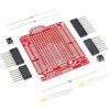
DescriptionThe SparkFun ProtoShield Kit lets you customize your own Arduino shield using whatever circuit you can come up with and then test it to make sure everything is working the way it should! The SparkFun ProtoShield Kit is based off the Arduino R3's footprint that allows you to easily incorporate it with favorite Arduino-based device.One of our favorite features with this version of the ProtoShield Kit is the solderable-like breadboard prototyping area! Half of this area was designed with a breadboard in mind. On the underside of the shield you will be able to see open jumper pads between each through hole to make a connection like a breadboard. Once you add a component, simply add a solder jumper between holes to make a connection. For those that prefer the standard prototyping pads, we left the other side(near the BlueSMiRF and Serial UART ports)as is.We have also moved the prototype testing components(those used to make sure your circuit works effectively)off of the "mainland" of the shield and onto a ProtoSnap styled, removable PCB. On this test area you will find soldering areas for the two yellow 3mm LEDs(as well as pins to control and power them), two 330 Ohm resistors, a 10K Ohm resistor, and a pushbutton.Note:Since this product is a kit, assembly and a basic knowledge of soldering will be required. The SparkFun ProtoShield Kit does not come pre-assembled.Get Started With the SparkFun ProtoShield Kit GuideFeaturesArduino R3 FootprintSoldering KitSolderable-Like BreadboardBlueSMiRF or Comparable 6-pin PinsDetachable Test Area
アズワン品番67-0422-25
 SparkFun MicroMod RP2040 ProcessorSPARKFUN
¥4,398税込¥4,838
1個
33日以内出荷
DescriptionThe SparkFun MicroMod Pi RP2040 Processor Board is a low-cost, high-performance board with flexible digital interfaces featuring the Raspberry Pi Foundation's RP2040 microcontroller. With the MicroMod M.2 connector, connecting your MicroMod Pi RP2040 Processor Board is a breeze. Simply match up the key on your processor's beveled edge connector to the key on the M.2 connector and secure it with a screw(included with all Carrier Boards).The RP2040 utilizes dual ARM Cortex-M0+ processors(up to 133MHz):264kB of embedded SRAM in six banks6 dedicated IO for SPI Flash(supporting XIP)30 multifunction GPIO:Dedicated hardware for commonly used peripheralsProgrammable IO for extended peripheral supportFour 12-bit ADC channels with internal temperature sensor(up to 0.5 MSa/s)USB 1.1 Host/Device functionalityThe RP2040 is supported with both C/C++ and MicroPython cross-platform development environments, including easy access to runtime debugging. It has UF2 boot and floating-point routines baked into the chip. The built-in USB can act as both device and host. It has two symmetric cores and high internal bandwidth, making it useful for signal processing and video. While the chip has a large amount of internal RAM, the board includes an additional external flash chip.MicroMod is a modular interface ecosystem that connects a microcontroller "processor board" to various "carrier board" peripherals. Utilizing the M.2 standard, the MicroMod standard is designed to easily swap out processors on the fly. Pair a specialized carrier board for the project you need with your choice of compatible processor!Get Started with the MicroMod RP2040 Processor GuideFeaturesRP2040 General FeaturesDual Cortex M0+ processors, up to 133 MHz264 kB of embedded SRAM in 6 banks6 dedicated IO for QSPI flash, supporting execute in place(XIP)30 programmable IO for extended peripheral supportSWD interfaceTimer with 4 alarmsReal time counter(RTC)USB 1.1 Host/Device functionalitySupported programming languagesMicroPythonC/C++Specific Peripherals made available on MicroMod RP20401x USB dedicated for programming and debug(Host capable)2x UARTs2x I2C2x SPI29x GPIO2x Digital Pins3x Analog Pins16x PWM128Mbit/16MB(external)flash memoryStatus LEDVIN Level ADC
アズワン品番67-0423-49
 SparkFun FM Tuner Evaluation Board - Si4703SPARKFUN
¥6,698税込¥7,368
1個
33日以内出荷
DescriptionThis is an evaluation board for the Silicon Laboratories Si4703 FM tuner chip. Beyond enabling you to tune in to FM radio stations, the Si4703 is also capable of detecting and processing both Radio Data Service(RDS)and Radio Broadcast Data Service(RBDS)information. The Si4703 even does a very good job of filtering and carrier detection. It also enables data such as the station ID and song name to be displayed to the user.Using this board, you will be able to pick up multiple stations just as well as with a standard FM radio. The board breaks out all major pins and makes it easy to incorporate this great chip into your next radio project. The power bus, the 3.3V and GND pins are broken out For communication. The breakout provides access to SDIO and SCLK for I2C communication while RST can be used for easy resetting. The SEN pin enables the user to change the mode of functionality of the IC. The last two pins broken out are GPIO1 and GPIO2 which can be used as general input/output pins, but also can be used for things like the RDS ready, seeking or tuning functions.Keep in mind, by plugging headphones into the 3.5mm audio jack, you effectively use the cable in your headphones as an antenna! Therefore, this board does not require an external antenna if using headphones or a 3.5mm audio cable longer than 3 feet.
アズワン品番67-0429-34
 PicoBuck LED DriverSPARKFUN
¥4,798税込¥5,278
1個
33日以内出荷
DescriptionThe PicoBuck LED Driver is an economical and easy to use driver that will allow you to control and blend three different LEDs on three different channels. By default, each channel is driven at 330mA; that current can be reduced by either presenting an analog voltage or a PWM signal to the board. Version 12 of the board adds a solderable jumper that can be closed to increase the maximum current to 660mA. The new voltage regulator also increased the voltage rating on the various components on the board, allowing it to be used up to the full 36V rating of the AL8805 part.Three signal inputs are provided for dimming control. You can use the PWM signal from an Arduino or your favorite microcontroller to dim each channel individually, or you can tie them all to the same PWM for simultaneous dimming. Dimming can be done by an analog voltage(20%-100% of max current by varying voltage from .5V-2.5V)or by PWM(so long as PWM minimum voltage is less than .4V and maximum voltage is more than 2.4V)for a full 0-100% range. A small jumper is provided for each channel to allow you to increase the drive strength from 330mA to 660mA. Two mounting holes for 4-40 or M3 screws are provided on either side of the board. They are perforated so they can be easily snapped off with a pair of pliers, if a smaller footprint is desired.Note:If you're going to use screw terminals, this board uses two different sizes. Check the related products for both sizes you'll need.Note:The PicoBuck LED Driver was made in collaboration with Ethan Zonca. A portion of each sale is given back to him.
アズワン品番67-0420-83
 LIDAR-Lite v3HPSPARKFUN
¥37,980税込¥41,778
1個
33日以内出荷
DescriptionLIDAR has never looked so good! This is the LIDAR-Lite v3HP, a compact, high-performance optical distance measurement sensor from Garmin(TM). The LIDAR-Lite v3HP istheideal optical ranging solution for drone, robot, or unmanned vehicle applications. Each sensor is housed in a durable, IPX7-rated housing and includes all the core features and user configurability of the popular LIDAR-Lite v3.The v3HP is very similar in function to that of the v3 but it can now sample faster at rates greater than 1kHz(where as the v3 is only capable of up to 500Hz). Another improvement is that this v3HP model is more power efficient with current consumption rates 40mA less than the v3(that's 65mA as opposed to 105mA while idle, and 85mA instead of 130mA while acquiring).Each LIDAR-Lite v3HP has a range of 1m to 40m and features an edge-emitting, 905nm(1.3 watts), single-stripe laser transmitter, 8m Radian beam divergence, and an optical aperture of 12.5mm. This version of the LIDAR-Lite still operates at 5VDC(6V max)with a peak power of 1.3W and still possesses an accuracy of +/- 2.5cm at >2m. On top of everything else, the LIDAR-Lite is user-configurable, allowing adjustment between accuracy, operating range and measurement time and can be interfaced via I2C or PWM with the attached 200mm cable.Note:CLASS 1 LASER PRODUCT CLASSIFIED EN/IEC 60825-1 2014. This product is in conformity with performance standards for laser products under 21 CFR 1040, except with respect to those characteristics authorized by Variance Number FDA-2016-V-2943 effective September 27, 2016.Get Started with the LIDAR-Lite v3HP GuideFeaturesResolution:1 cmTypical accuracy:+/- 2.5cm at distances greater than 2 meters(Refer to operating manual for complete operating specifications)Range:1m to 40mUpdate rate:Greater than 1kHzInterface:I2C or PWMPower(operating voltage):4.75-5VDC; 6V MaxCurrent consumption:65ma idle; 85ma during acquisitionOperating temperature:-20℃ to 60℃Laser wave length/Peak power:905nm/1.3WBeam divergence:8m RadianOptical aperture:12.5mmWater rating:IPX7Unit dimensions:24.5mm×53.5mm×33.5mm(1.0in×2.1in×1.3in)Weight:34g(1.2oz)
アズワン品番67-0426-76
 JST Right-Angle Connector - SMD 2-Pin BlackSPARKFUN
¥209税込¥230
1個
33日以内出荷
DescriptionThis is a two pin, compact surface mount JST connector. We really like the solid locking feeling and high current rating on these small connectors. We use these all the time as battery connectors.
アズワン品番67-0425-09
 High Speed Optoisolator - 6N137SPARKFUN
¥329税込¥362
1個
33日以内出荷
DescriptionThis diode-transistor photocouplers consist of an LED, optically coupled to a high speed photodetector to transmit electrical signals between circuits while still isolating your system from higher voltages. The 6N137 optoisolator is presented in an 8-pin DIP package.The output features is an open collector and coupler parameters are guaranteed over the temperature range from -40℃~5℃. The internal shield provides a guaranteed Common Mode Transient Immunity(typical)10KV/μs.FeaturesHigh Speed:10MBdCommon Mode Rejection:10KV/μs
アズワン品番67-0421-33
 SparkFun Thing Plus - RP2040SPARKFUN
¥6,698税込¥7,368
1個
33日以内出荷
DescriptionThe SparkFun Thing Plus - RP2040 is a low-cost, high performance board with flexible digital interfaces featuring the Raspberry Pi Foundation's RP2040 microcontroller. Besides the Thing Plus orFeatherfootprint(with 18 GPIO pins), the board also includes an SD card slot, 16MB(128Mbit)flash memory, a JST single cell battery connector(with a charging circuit and fuel gauge sensor), an addressable WS2812 RGB LED, JTAG PTH pins, four(4-40 screw)mounting holes, and our signature Qwiic connector.The RP2040 contains two ARM Cortex-M0+ processors(up to 133MHz)and features:264kB of embedded SRAM in six banks6 dedicated IO for SPI Flash(supporting XIP)30 multifunction GPIO:Dedicated hardware for commonly used peripheralsProgrammable IO for extended peripheral supportFour 12-bit ADC channels with internal temperature sensor(up to 0.5 MSa/s)USB 1.1 Host/Device functionalityThe RP2040 is supported with both C/C++ and MicroPython cross-platform development environments, including easy access to runtime debugging. It has UF2 boot and floating-point routines baked into the chip. While the chip has a large amount of internal RAM, the board includes an additional 16MB of external QSPI flash memory to store program code.The SparkFun Qwiic Connect System is an ecosystem of I2C sensors, actuators, shields and cables that make prototyping faster and less prone to error. All Qwiic-enabled boards use a common 1mm pitch, 4-pin JST connector. This reduces the amount of required PCB space, and polarized connections mean you can't hook it up wrong.Get Started With the Thing Plus RP2040 Hookup GuideFeaturesSparkFun Thing Plus - RP2040 FeaturesRaspberry Pi Foundation's RP2040 microcontroller16MB QSPI Flash MemoryJTAG PTH PinsThing Plus(or Feather)Form-Factor:18[1]x Multifunctional GPIO Pins[2]Four available 12-bit ADC channels with internal temperature sensor(500kSa/s)Up to eight 2-channel PWMUp to two UARTsUp to two I2C busesUp to two SPI busesUSB-C Connector:USB 1.1 Host/Device functionality2-pin JST Connector for a LiPo Battery(not included)500mA charging circuitQwiic ConnectorButtons:BootResetLEDs:PWR- Red 3.3V power indicatorCHG- Yellow battery charging indicator25- Blue status/test LED(GPIO 25)WS2812- Addressable RGB LED(GPIO 08)Four Mounting Holes:4-40 screw compatibleDimensions:2.3"×0.9"RP2040 General FeaturesDual Cortex M0+ processors, up to 133 MHz264 kB of embedded SRAM in 6 banks6 dedicated IO for QSPI flash, supporting execute in place(XIP)30 programmable IO for extended peripheral supportSWD interfaceTimer with 4 alarmsReal time counter(RTC)USB 1.1 Host/Device functionalitySupported programming languagesMicroPythonC/C++1.Note:GPIO 08is not included in this count, as it passes through the WS2812 addressable RGB LED first.GPIO 07andGPIO 23are counted as a single GPIO because they are tied together.2.Note:The GPIO pins are programmable so you can reconfigure the pins! Check out the RP2040 datasheet for more information on the GPIO functionality.
アズワン品番67-0423-56
 SparkFun RTK SurveyorSPARKFUN
¥109,800税込¥120,780
1個
33日以内出荷
DescriptionThe SparkFun RTK Surveyor is an easy to use GNSS receiver for centimeter-level positioning. Perfect for surveying, this preprogrammed device can also be used for autonomous driving, navigation, asset tracking and any other application where there is a clear view of the sky. The RTK Surveyor can also be used as a base station. With the flick of a switch, two RTK Surveyors can be used to create an RTK system capable of 14mm horizontal positional accuracy. The built-in Bluetooth(R)connection via an ESP32 WROOM enables the user to use the RTK Surveyor with their choice of GIS application on a phone or tablet. The built in battery allows field use for up to four hours and is compatible with common USB battery banks.This device can be used in four modes:GNSS Positioning(~30cm accuracy)GNSS Positioning with RTK(1.4cm accuracy)GNSS Base StationGNSS Base Station NTRIP ServerIn Position mode the device receives L1/L2 signals from a user-provided antenna and the high-grade GNSS receiver provides lat/long and altitude with accuracies around 300mm.In Positioning with RTK mode the device receives L1/L2 signals from the antenna and correction data from a base station. The correction data can be obtained from a cellular link to online correction sources or over a radio link to a 2nd RTK Surveyor setup as a base station.In Base Station mode the device is mounted to a temporary position(like a tripod)and begins transmitting correction data over a radio or internet connection. A base is often used in conjunction with a second unit set to 'Positioning with RTK' to obtain the 14mm relative accuracy.In Base Station NTRIP Server mode the device is mounted to a semi or permanently fixed position(like a roof)and connects over WiFi to transmit the correction data to a NTRIP caster so that any rover can access the correction data over a cellular or internet connection. This type of base is a very easy way to setup a very precise absolute correction source.Two cables are provided with the RTK Surveyor allowing a user to plug on our easy to use Serial Telemetry Radios or their own radio link. If a local correction source is within 10km, a user can also use their phone to provide correction data over the Bluetooth(R)link(no external radio needed!).Note:The SparkFun RTK Surveyor is just the enclosed device and does NOT include an antenna, serial telemetry radio, or associated mounting pieces. These items will need to be purchased separately from the Hookup Accessories below.Get Started With the SparkFun RTK Surveyor GuideFeaturesGNSS Receiver:ZED-F9PConcurrent reception of GPS, GLONASS, Galileo and BeiDouReceives both L1C/A and L2C bandsCurrent:68mA - 130mA(varies with constellations and tracking state)Time to First Fix:25s(cold), 2s(hot)Max Navigation Rate:PVT(basic location over UBX binary protocol)- 25HzRTK - 20HzRaw - 25HzHorizontal Position Accuracy:2.5m without RTK0.010m with RTKMax Altitude:50km(31 miles)Max Velocity:500m/s(1118mph)Bluetooth(R)Transceiver:ESP32 WROOMXtensa(R)dual-core 32-bit LX6 microprocessorUp to 240MHz clock frequency16MB of flash storage520kB internal SRAMIntegrated 802.11 BGN WiFi transceiverIntegrated dual-mode Bluetooth(R)(classic and BLE)Hardware accelerated encryption(AES, SHA2, ECC, RSA-4096)2.5 μA deep sleep currentOverall DeviceInternal Battery:LiPo 1000mAh with 500mA chargingRadio Port:3.3V TTL Serial(57600bps RTCM TX/RX)Data Port:3.3V TTL Serial(115200bps NMEA)Weight:132g(entire device including battery)Dimensions:118mm×79mm×30mm(4.7in×3.1in×1.2in)1x Qwiic Connector1x microSD Socket for optional loggingChanges:This version(which replaces SPX-17369)uses a reinforced edge mount SMA connector for better resiliency when a fixed 'stub' antenna is used.
アズワン品番67-0423-95
 SparkFun QwiicBus KitSPARKFUN
¥11,980税込¥13,178
1個
5日以内出荷
DescriptionThe SparkFun QwiicBus Kit comes with everything you need to get started with the SparkFun QwiicBus system in one handy package. The kit includes two QwiicBus EndPoints, one MidPoint and two 3ft Ethernet cables.The SparkFun QwiicBus EndPoint is the fastest and easiest way to extend the range of your I2C communication bus. Both boards use NXP's PCA9615 IC, which converts the two default I2C signals into four differential signals, two for SCL and two for SDA. The differential signals are sent over an Ethernet cable, which attaches to the breakout through the on-board RJ-45 connectors The differential signaling allows the I2C signals to reach distances of up to 100ft. while still maintaining their signal integrity! To make it even easier to get your readings, all communication is enacted exclusively via I2C, utilizing our handy Qwiic system so no soldering is required to connect it to the rest of your system. However, we still have broken out 0.1"-spaced pins in case you prefer to use a breadboard.The QwiicBus MidPoint works in tandem with the QwiicBus Endpoint so you can easily tap into it to drop in devices wherever you would like.The SparkFun Qwiic Connect System is an ecosystem of I2C sensors, actuators, shields and cables that make prototyping faster and less prone to error. All Qwiic-enabled boards use a common 1mm pitch, 4-pin JST connector. This reduces the amount of required PCB space, and polarized connections mean you can't hook it up wrong.Get Started with the SparkFun QwiicBus Guide
アズワン品番67-0424-60
 SparkFun MicroMod Qwiic Carrier Board - SingleSPARKFUN
¥2,898税込¥3,188
1個
33日以内出荷
DescriptionThe MicroMod Qwiic Carrier Board can be used to rapidly prototype with other Qwiic devices. The MicroMod M.2 socket provides users the freedom to experiment with any processor board in the MicroMod ecosystem. This board also features two Qwiic connectors and four 4-40 screw inserts to connect and mount Qwiic devices.This version of the SparkFun MicroMod Qwiic Carrier Board features a single port for our standard 1in. by 1in. Qwiic Breakouts. However, you aren't beholden to attaching just one Qwiic breakout since you are able to stack the boards on top of each other, allowing you to hook up a full circuit of Qwiic sensors and accessories to fully utilize your next project!MicroMod is a modular interface ecosystem that connects a microcontroller "processor board" to various "carrier board" peripherals. Utilizing the M.2 standard, the MicroMod standard is designed to easily swap out processors on the fly. Pair a specialized carrier board for the project you need with your choice of compatible processor!Get Started With the MicroMod Qwiic Carrier Board GuideFeaturesM.2 MicroMod(Processor Board)ConnectorUSB-C Connector3.3V 1A Voltage RegulatorQwiic ConnectorsBoot/Reset ButtonsCharge CircuitFour 4-40 Inserts
アズワン品番67-0423-50
 PureThermal Mini Pro JST-SR with FLIR Lepton 3.5SPARKFUN
¥119,800税込¥131,780
1個
33日以内出荷
DescriptionThe new PureThermal Mini Pro JST-SR with Thermal by FLIR is a hackable thermal camera for the FLIR Lepton thermal imaging camera core. Just like its PureThermal 2 predecessor, it ships pre-configured to operate as a plug-and-play UVC 1.0 USB thermal webcam that will work with standard webcam and video apps on all major platforms using a JST-SR to USB Cable, or your own custom cable. For developers, its reference firmware and viewer software are open source.It has multiple connection options such as solder straight to the board or a custom cable using the JST-SR port. The PTMini Pro also features four mounting holes, less complex circuitry, and perhaps best of all, USB DFU. This is a development kit ready to be embedded into a production system.Each board comes with a FLIR Lepton 3.5.The FLIR Lepton(R)is a radiometric-capable LWIR camera solution that is smaller than a dime, fits inside a smartphone, and is one tenth the cost of traditional IR cameras. Using focal plane arrays of either 160x120 or 80x60 active pixels, Lepton easily integrates into native mobile-devices and other electronics as an IR sensor or thermal imager. The radiometric Lepton captures accurate, calibrated, and noncontact temperature data in every pixel of each image.FeaturesPureThermal:Compatible with all production FLIR Leptons, including radiometric 2.5 and 3.5 cores9 Hz color video over usb using the USB UVC classSTM32F412 ARM microprocessor - execute on-board image processing without need for an external systemOpen source reference firmware:GroupGets PureThermal GithubWorks with GetThermal - our custom open source thermal video display software for macOS and Linux with radiometric supportDFU over USB using a JST-SR port to USB cable, or a modified USB cable and the through holes.Four mounting holesCompact form-factor ready to be embedded into production systemsFLIR Lepton 3.5:Thermal sensitivity:< 50 mK(0.050℃)Spectral Range:8 - 14 microns(nominal)Long Wave Infrared(LWIR)Resolution:160h×120v pixelsRadiometric Accuracy - High Gain Mode:Greater of +/- 5℃ or 5%(typical); Low Gain Mode:Greater of +/- 10℃ or 10%(typical)Scene Dynamic Range - High Gain Mode:-10° to +140℃; Low Gain Mode:-10° to +400℃(at room temperature), -10° to +450℃(typical)Pixel Size:12 micrometersFrame Rate:8.7 Hz(effective)Output Format:User-selectable 14-bit, 8-bit(AGC applied), or 24-bit RGB(AGC and colorization applied)Horizontal Field of View(HFOV):57°Lens Type:f/1.1Size(w×l×h):10.50×12.70×7.14 mmWeight:0.9 gramsPower Consumption:150 mW typical, 650 mW during shutter event, 5mW standbyOptimum Operating Temperature Range:-10℃ to + 80℃
アズワン品番67-0423-44
 Garmin LIDAR-Lite v4 LED - Distance Measurement SensorSPARKFUN
¥19,980税込¥21,978
1個
33日以内出荷
DescriptionThe LIDAR-Lite v4 LED sensor is the next step in the LIDAR-Lite line. A small, lightweight, low-power optical ranging sensor. It's the first to incorporate ANT profile wireless networking technology into an optical sensor. Its built-in nRF52840 processor means that developers can create custom applications, or be operated as a stand-alone device right out of the box by using the preloaded stock application.Like the LIDAR-Lite v3 and LIDAR-Lite v3HP sensors; it can also be directly connected to an external micro-controller running a custom user application. As such, it provides a highly adaptable option for OEM and maker applications in robotics, Internet of Things, and unmanned vehicles ― or any application where an ultrasonic sensor might otherwise be used. It's perfect as the basic building block for applications where wireless capabilities, small size, light weight, low power consumption and high performance are important factors in a short-range, 10-meter, optical distance measuring sensor.The LIDAR-Lite v4 requires an external 5VDC power source and soldering is required. This Time-of-Flight ranging module uses a LED and optics for ranging. It does not use a laser; therefore, it is inherently eye-safe under normal usage.FeaturesResolution:1 cmMeasurement repeatability:As measured indoors to a 90% reflective target1 cm is equivalent to 1 standard deviationUsing "high accuracy" mode, with averaging:+/- 1 cm to 2 meters+/- 2 cm to 4 meters+/- 5 cm to 10 metersRange:5 cm to 10 meters(as measured from back of unit)Update rate:I2C = >200 Hz typicalANT(R)= up to 200 Hz to a 90% target indoors at 2m in normal operating modeInterface:I2C or ANT; user configurable for SPI using the Nordic SDKPower(operating voltage):4.75 - 5.25 VDCCurrent consumption:2mA idle, 85mA during acquisitionOperating temperature:-20 to 60° CLED wavelength:940 nmBeam divergence:4.77°Optical aperture:14.9 mmUnit size(HxWxD):2.1"×0.8"×0.9"(52.2×21.2×24.0 mm)Weight:14.6 g(0.5 oz)
アズワン品番67-0427-09
 モータードライバSPARKFUN
¥4,398税込¥4,838
1個
33日以内出荷
DescriptionThe TB6612FNG Motor Driver can control up to two DC motors at a constant current of 1.2A(3.2A peak). Two input signals(IN1 and IN2)can be used to control the motor in one of four function modes:CW, CCW, short-brake and stop. The two motor outputs(A and B)can be separately controlled, and the speed of each motor is controlled via a PWM input signal with a frequency up to 100kHz. The STBY pin should be pulled high to take the motor out of standby mode.Logic supply voltage(VCC)can be in the range of 2.7--5.5VDC, while the motor supply(VM)is limited to a maximum voltage of 15VDC. The output current is rated up to 1.2A per channel(or up to 3.2A for a short, single pulse).This little board comes with all components installed as shown. Decoupling capacitors are included on both supply lines. All pins of the TB6612FNG are broken out to two 0.1" pitch headers; the pins are arranged such that input pins are on one side and output pins are on the other.Note:If you are looking for the SparkFun Motor Driver with headers, it can be found here or in theSimilar Productsbelow.Get Started With the Motor Driver Hookup GuideFeaturesPower supply voltage:VM = 15V max, VCC = 2.7--5.5VOutput current:Iout = 1.2A(average)/ 3.2A(peak)Standby control to save powerCW/CCW/short-brake/stop motor control modesBuilt-in thermal shutdown circuit and low-voltage detecting circuitAll pins of the TB6612FNG broken out to 0.1" spaced pinsFiltering capacitors on both supply lines
アズワン品番67-0395-99
 SparkFun Qwiic Keypad - 12 ButtonSPARKFUN
¥3,598税込¥3,958
1個
33日以内出荷
DescriptionKeypads are very handy input devices, but who wants to tie up seven GPIO pins, wire up handful of pull-up resistors, and write firmware that wastes valuable processing time scanning the keys for inputs? The SparkFun Qwiic Keypad comes fully assembled and makes the development process for adding 12 button keypad easy. No voltage translation or figuring out which I2C pin is SDA or SCL, just plug and go! Utilizing our handy Qwiic system, no soldering is required to connect it to the rest of your system. However, we still have broken out 0.1"-spaced pins in case you prefer to use breadboard.Each of the keypad's 12 buttons has been labeled 1, 2, 3, 4, 5, 6, 7, 8, 9, 0, *, and and has been formatted to into the same layout as telephone keypad with each keypress resistance ranging between 10 and 150 Ohms. The Qwiic Keypad reads and stores the last 15 button presses in First-In, First-Out(FIFO)stack, so you don't need to constantly poll the keypad from your microcontroller. This information, then, is accessible through the Qwiic interface. The SparkFun Qwiic Keypad even has software configurable I2C address so you can have multiple I2C devices on the same bus.NOTE:The I2C address of the Qwiic Keypad is 0x4B and is jumper selectable to 0x4A(software-configurable to any address). multiplexer/Mux is required to communicate to multiple Qwiic Keypad sensors on single bus. If you need to use more than one Qwiic Keypad sensor consider using the Qwiic Mux Breakout.The SparkFun Qwiic connect system is an ecosystem of I2C sensors, actuators, shields and cables that make prototyping faster and less prone to error. All Qwiic-enabled boards use common 1mm pitch, 4-pin JST connector. This reduces the amount of required PCB space, and polarized connections mean you can't hook it up wrong.Get Started with the SparkFun Qwiic Keypad Hookup GuideFeaturesSoftware Selectable Slave AddressLow Power ATtiny85 controllerButton Presses w/ Time StampDefault I2C Address:0x4B2x Qwiic Connector
アズワン品番67-0421-41
 LilyPad ProtoSnap PlusSPARKFUN
¥12,980税込¥14,278
1個
33日以内出荷
DescriptionThe LilyPad ProtoSnap Plus is a sewable electronics prototyping board that you can use to explore circuits and programming, then break apart to make an interactive fabric or wearable project. Programming the ProtoSnap Plus is easy with the free Arduino software you'll need to program the ATmega32U4 on LilyPad USB Plus at the heart of the board. Once you've installed the software, you'll be able to write and upload your own programs to the board, making it do almost anything you want.At the center of the ProtoSnap Plus is the LilyPad USB Plus microcontroller, pre-wired to a LilyPad board including a LilyPad Light Sensor, LilyPad Buzzer, LilyPad Button Board, four pairs of colored LilyPad LEDs and a LilyPad Slide Switch. Because these components are connected together on the ProtoSnap board, you can test out your project ideas before you sew. The ProtoSnap Plus also includes expansion ports that let you sew your wearables together or use alligator cables to easily connect external sensors and components. After testing out your coding ideas using the attached LilyPad pieces, you can break apart the prototyping board and sew them into your project!Please be aware that the Lilypad ProtoSnap Plus isNOT supported on Windows 7/8due to a lack of support drivers for those specific OS's.Note:A portion of this sale is given back to Dr. Leah Buechley for continued development and education in e-textiles.Get Started with the LilyPad ProtoSnap Plus Guide
アズワン品番67-0422-45
 USB Female Type B ConnectorSPARKFUN
¥339税込¥373
1個
33日以内出荷
USB Type 'B' Female connector. The 4 connection pins have .1" spacing allowing it to be inserted into development boards and perf boards with mild modification. You can either drill two 80mil holes for the support posts、or cut them off completely.
アズワン品番67-0454-07
 Thermocouple Connector - PCC-SMP-KSPARKFUN
¥3,398税込¥3,738
1個
6日以内出荷
DescriptionThis Thermocouple Connector is perfect for bridging the gap between Type-K thermocouples with standard connectors with a PCB. This little connector is actually the exact part we recommend using with our SparkFun Thermocouple Breakout! Each
アズワン品番67-0425-14
 Elektor STM32 Nucleo Starter KitSPARKFUN
¥15,980税込¥17,578
1個
33日以内出荷
DescriptionThe Elektor STM32 Nucleo Starter Kit is the perfect entry point into the world of the widely popular STM32 microcontroller line. This bundle covers many projects using most features of the STM32 Nucleo development boards with the full softw
アズワン品番67-0424-72
 SparkFun Soil Moisture SensorSPARKFUN
¥1,698税込¥1,868
1個
33日以内出荷
DescriptionThe SparkFun Soil Moisture Sensor is a simple breakout for measuring the moisture in soil and similar materials. The soil moisture sensor is pretty straight forward to use. The two large exposed pads function as probes for the sensor, toge
アズワン品番67-0426-51
 Kitronik MI:power Board V2SPARKFUN
¥2,598税込¥2,858
1個
33日以内出荷
DescriptionThe MI:power board for the BBC micro:bit brings real portability to your wearable projects. The stylish, lightweight PCB is designed to fit snugly against the BBC micro:bit and features a built-in buzzer and 3V coin cell holder. This la
アズワン品番67-0423-58
 Resistor Network - 330 Ohm 6-pin bussedSPARKFUN
¥258税込¥284
1個
5日以内出荷
仕様●抵抗値:330Ω●ピン数:6ピンアズワン品番67-0453-16
 SparkFun RJ11 BreakoutSPARKFUN
¥639税込¥703
1個
33日以内出荷
DescriptionThis is the SparkFun RJ11 Breakout, two simple breakout boards for the common 6-pin RJ11 connector. These little boards can easily have one of our RJ11 6-Pin Connectors to work with common telephone cables. Each board features standard B/R/Y/G(Black/Red/Yellow/Green)labels on the top of the board to match a standard telephone wire. Additionally, each board has pin numbers on the back side that match with the pins on the connector.Each breakout consists of two boards -- one for each end of the connections -- as well as mounting holes to help you secure your project in place.
アズワン品番67-0420-01
 SparkFun Qwiic Shield for TeensySPARKFUN
¥1,098税込¥1,208
1個
33日以内出荷
DescriptionThe SparkFun Qwiic Shield for Teensy provides you with a quick and easy way to enter into SparkFun's Qwiic ecosystem with your Teensy boards. This shield is sized to work with the footprint of Teensy 4.0, Teensy 3.2, and Teensy LC. This shield connects the I2C bus(GND, 3.3V, SDA, and SCL)on your Teensy to four SparkFun Qwiic connectors(two horizontally and two vertically mounted). The Qwiic ecosystem allows for easy daisy chaining so, as long as your devices are on different addresses, you can connect as many Qwiic devices as you'd like.We have also added a "PROG" button on this shield that is electrically parallel with the "PROG" button on the Teensy Boards so you can choose to enter Programming mode using either the button on your Teensy or the button on the shield.The Qwiic Shield for Teensy comes with the Teensy Header Kit and you will need to solder the headers to the shield and, if necessary, to your Teensy board. Take care to match the markings on the Qwiic Shield to the appropriate pins on your Teensy to avoid possibly damaging your boards.The SparkFun Qwiic Connect System is an ecosystem of I2C sensors, actuators, shields and cables that make prototyping faster and less prone to error. All Qwiic-enabled boards use a common 1mm pitch, 4-pin JST connector. This reduces the amount of required PCB space, and polarized connections mean you can't hook it up wrong.Get Started with the SparkFun Qwiic Shield for Teensy Hookup GuideFeaturesTeensy 4.0, 3.2, or LC Footprint Compatible4x Qwiic Connection Ports"PROG" Button w/ satisfying tactile feedbackI2C Jumper3.3V and GND Buses
アズワン品番67-0423-21
 SparkFun MicroMod Update ToolSPARKFUN
¥1,498税込¥1,648
1個
33日以内出荷
DescriptionThe SparkFun MicroMod Update Tool is built to interface with the MicroMod Asset Tracker Carrier Board and also makes it simple to communicate directly with the u-blox SARA-R510M8S module using u-blox's sophisticated m-center cellular evaluation software. If you're familiar with u-center, u-blox's GNSS evaluation software, you'll know how excellent their software is. m-center is every bit as good. Attach a USB-C cable and away you go!The Update Tool is not a full MicroMod Processor Board, it is much simpler than that. It has a CH340C USB-Serial converter on it which gives you full access to all eight pins of the SARA-R5's UART interface via the Asset Tracker's USB-C connector. Think of it as a bridge from USB to serial.The Update Tool features eight pairs of Plated Through Hole connections for the UART signals. You can use these to connect directly to the SARA UART using 3.3V signals if you want to. The split pads on the rear of the Tool can be opened to isolate the CH340C completely; the pins nearest the M.2 will link straight to the SARA UART.Get Started with the MicroMod Update Tool Hookup GuideFeaturesCH340C USB-Serial converterEight pairs of Plated Through Hole connections with split pad jumper links for:Serial Transmit(TX)Serial Receive(RX)Request To Send(RTS)Clear To Send(CTS)Data Terminal Ready(DTR)Data Set Ready(DSR)Ring Indicator(RI)Data Carrier Detect(DCD)LED indicator for:Power(3.3V)
アズワン品番67-0423-52
 Spade Connector Wire - 3ft, Female 2 PackSPARKFUN
¥539税込¥593
1個
33日以内出荷
DescriptionThese simple 24AWG wires are terminated with a female insulated spade connector at one end and a braided wire lead at the other. Each wire is 3 feet long and is capable of supporting a high voltage of 300VDC. Each order comes in a pack of two!We use these cables almost exclusively on our Spectacle Button Board, but that doesn't mean you can't find a different use for them!Documentation:Dimensional DrawingFeatures3ft(0.9m)length
アズワン品番67-0420-31
 Official Raspberry Pi 4 Case - Black/GraySPARKFUN
¥1,898税込¥2,088
1個
33日以内出荷
DescriptionThe official case for the Raspberry Pi 4. This case ships as two parts made of ABS plastic with access to all USB, HDMI, Audio/Video, USB and Ethernet ports. In addition, a slot on the bottom gives access to the MicroSD card. The top and bottom parts are press fit and comes in two-tone black and gray.
アズワン品番67-0426-07
 Bourns Absolute Encoder EAW0J-B24-AE0128LSPARKFUN
¥3,198税込¥3,518
1個
33日以内出荷
DescriptionThe Bourns Absolute Encoder is a digital control knob that provides 128 unique results evenly spaced around a full circle. It is designed as a control panel knob but can be adapted for other uses. This can be a good alternative to using a potentiometer and analog pin, as this allows for full-turn and multi-turn operation.It differs from the more common incremental rotary encoder which has only two or four values in a rotation and is designed to measure full rotations and direction. This measuresanglesand absolute position is maintained between power cycles.Features128 rotary positions360 degree continuous rotationRotational life - 50,000 revolutions(min)Max RPM - up to 120Absolute digital output will retain its last position between power cycles or in the event of a power failureThreaded M9x0.75 in. bushing3/4 in. rotating encoder shaftRear mount terminals
アズワン品番67-0421-27
 Qwiic Cable - Grove Adapter 100mmSPARKFUN
¥659税込¥725
1個
33日以内出荷
DescriptionWith the SparkFun Qwiic Connect System expanding every day, we want to make sure it becomes as accessible as possible but we understand there are other systems that can compliment it out there. The Qwiic to Grove Adapter Cable allows interoperability between the SparkFun Qwiic Connect System and the I2C based Grove boards from Seeed Studio. Now you can plug Seeed Studio boards you may have onto the Qwiic bus or you can use this cable to introduce Qwiic sensors, inputs, and outputs into your Grove system.Note:The Grove system has a variety of different signal systems that use the same connector. This cableonlyworks with the I2C variety.The SparkFun Qwiic connect system is an ecosystem of I2C sensors, actuators, shields and cables that make prototyping faster and less prone to error. All Qwiic-enabled boards use a common 1mm pitch, 4-pin JST connector. This reduces the amount of required PCB space, and polarized connections mean you can't hook it up wrong.FeaturesLength:100mm
アズワン品番67-0425-61
 LilyPad Rainbow LED 6 ColorsSPARKFUN
¥1,198税込¥1,318
1個
33日以内出荷
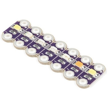
DescriptionThis is the LilyPad Rainbow LED strip, with seven LilyPad LEDs that are still attached to one another, letting you snap LEDs apart at your leisure to sew into clothing or whatever else you can dream up.The LilyPad Rainbow LED features seven individual LEDs in six unique colors(Red, Blue, Green, Yellow, Pink, and White). Text has been added to the back of each board to indicate its color. Due to popular request, we have included two white LEDs instead of just one.Note:A portion of this sale is given back to Dr. Leah Buechley for continued development and education in e-textiles.
アズワン品番67-0422-27
 SparkFun Real Time Clock Module - RV-1805 QwiicSPARKFUN
¥4,698税込¥5,168
1個
33日以内出荷
DescriptionGet with the times, already! This SparkFun Real Time Clock(RTC)Module is a Qwiic-enabled breakout board for the RV-1805 chipset. The RTC is ultra-low power(running at only about 22nA in its lowest power setting)so it can use a supercapacitor for backup power instead of a normal battery. This means you get plenty of charge and discharge cycles without any degradation to the "battery." To make it even easier to get your readings, all communication is enacted exclusively via I2C, utilizing our handy Qwiic system so no soldering is required to connect it to the rest of your system. However, we still have broken out 0.1"-spaced pins in case you prefer to use a breadboard.This RTC module's built in RV-1805 has not one, but two internal oscillators:a 32.768kHz tuning fork crystal and a low power RC based oscillator and can automatically switch between the two using the more precise crystal to correct the RC oscillator every few minutes. This feature allows the module to maintain a very accurate date and time with the worst case being +/- about three minutes over a year. The RV-1805 also has a built in trickle charger so as soon as the RTC is connected to power the it will be fully charged in under 10 minutes and has the ability to switch power to other systems allowing it to directly turn on or off a power hungry device such as a microcontroller or RF engine.There is also the option to add a battery to the board if the supercapacitor just isn't going keep your project powered long enough(keep in mind, the supercap can hypothetically make the board keep time for around 35 days), you can solder on an external battery. That means you can let board sit with no power or connection to the outside world and the current hour/minute/second/date will be maintained.Note:The I2C address of the RV-1805 is 0x69 and is hardware defined. A multiplexer/Mux is required to communicate to multiple RV-1805 sensors on a single bus. If you need to use more than one RV-1805 sensor consider using the Qwiic Mux Breakout.The SparkFun Qwiic connect system is an ecosystem of I2C sensors, actuators, shields and cables that make prototyping faster and less prone to error. All Qwiic-enabled boards use a common 1mm pitch, 4-pin JST connector. This reduces the amount of required PCB space, and polarized connections mean you can't hook it up wrong.Get Started with the RV-1805 Real Time Clock Module GuideFeaturesOperating Voltage(Startup):1.6V - 3.6VOperating Voltage(Timekeeping):1.5V - 3.6VOperating Temperature:-40℃ - 85℃Time Accuracy:±2.0 ppmCurrent Consumption:22nA(Typ.)I2C Address:0xD2Supercapacitor for Backup Power2x Internal Oscillators2x Qwiic Connectors
アズワン品番67-0420-02
 SparkFun LTE CAT M1/NB-IoT Shield - SARA-R4SPARKFUN
¥26,980税込¥29,678
1個
33日以内出荷
DescriptionThe SparkFun LTE CAT M1/NB-IoT Shield equips your Arduino or Arduino-compatible microcontroller with access to data networks across the globe. This shield adds wireless, high-bandwidth cellular functionality to your IoT project while maintaining low power consumption and small footprint. The SparkFun LTE CAT M1/NB-IoT Shield is based off the Arduino R3's footprint that allows you to easily incorporate it with favorite Arduino-based device.At the heart of the LTE Cat M1/NB-IoT shield is u-blox SARA-R410M-02B LTE Cat M1/NB-IoT modem. Cat M1(Category M1)and NB-IoT(Narrowband IoT)are both Low Power Wide Area Network(LPWAN)technologies that are designed to provide cellular communication to small IoT devices. They operate on LTE network bands just like most smartphones, and should be supported by most cellular network carriers. The u-blox SARA-R4 module communicates over UART via simple AT command set. We've provided library to help you get started with everything from sending SMS text messages to communicating with servers over TCP/IP connection. Additionally, both the module and library support an I2C GPS interface via Qwiic connector, so you can plug in u-blox GPS module and start remotely tracking your project.Each SparkFun LTE CAT M1/NB-IoT Shield also includes ceramic, Molex 1462000001 SMD antenna. The antenna has gain of 3.8dBi around 1.7GHz to 2.7GHz. However, if you would prefer to use an external antenna, we have provided U.FL connector that can be utilized by simply slicing through jumper with hobby knife.Please be aware that there are few extra parts required to get this shield fully functioning, other than an Arduino-based device. First, you'll need to supply your own SIM card, such as this one from Hologram(we do also offer this shield with an included one as well)and your own headers which will need to be soldered on.Note:Be sure to check theHardware Overviewsection in the Hookup Guide for compatible GPS modules. The onboard Qwiic connector is only designed to support u-blox-based GPS modules. It does not support any other GPS modules or sensors. We are continuing to add more modules so be sure to check back every so often to find out more!Need custom board?This component can be found in SparkFun's La Carte board builder. You can have custom design fabricated with this component and your choice of hundreds of other sensors, actuators and wireless devices delivered to you in just few weeks.Get Started with the SparkFun LTE CAT M1/NB-IoT Shield GuideDocumentsSchematicEagle FilesHookup GuideDatasheetsSARA-R4Ceramic AntennaSARA-R4 AT Command SetArduino LibraryGitHub
アズワン品番67-0420-75
 Macchina A0 OBD-II Development ModuleSPARKFUN
¥28,980税込¥31,878
1個
33日以内出荷
DescriptionThe A0 in the latest in Macchina's line of OBD-II interfaces. The A0 uses the power of the ESP32 BLE and WiFi module to allow for wireless access to the OBD-II port most modern cars have.The Macchina A0 module plugs directly into the OBD-II port found in most modern cars and receives its power from the port. From there, one can interface with the device through a few different methods. The easiest is with software such as SavvyCAN, Torque Lite on Android. Besides getting all on board diagnostic information, you're able to control certain aspects of the car and create cool projects such as dash-mounted, shift lights. The A0 can also be programmed in the Arduino IDE, so there's plenty of possibilities to customize the device for what you want to do with your car!FeaturesODB-II compatibility with all modern cars(1996 or newer)Pre-loaded with SavvyCAN for plug and play(wireless!)reverse engineeringWiFi and Bluetooth(R)FunctionalityESP32 ProcessorSuper bright RGB LEDCAN Communication FunctionalityProgrammable with the Arduino IDE
アズワン品番67-0423-39
 SparkFun 16 Output I/O Expander Breakout - SX1509SPARKFUN
¥1,998税込¥2,198
1個
33日以内出荷
DescriptionAre you low on I/O? No problem! The SX1509 Breakout is 16-channel GPIO expander with an I2C interface that means with just two wires, your microcontroller can interface with 16 fully configurable digital input/output pins. But the SX1509 can do so much more than just simple digital pin control. It can produce PWM signals, so you can dim LEDs. It can be set to blink or even breathe pins at varying rates. This breakout is similar to multiplexer or "mux," in that it allows you to get more IO from less pins. And, with built-in keypad engine, it can interface with up to 64 buttons set up in an 8x8 matrix.Two headers at the top and bottom of the breakout board function as the input and control headers to the board. This is where you can supply power to the SX1509, and where your I2C signals SDA and SCL will terminate. GPIO and power buses are broken out in every-which direction, and configurable jumpers cover most of the rest of the board.Since the I/O banks can operate between 1.2V and 3.6V(5.5V tolerant)independent of both the core and each other, this device can also work as level-shifter. The SX1509 breakout makes it easy to prototype so you can add more I/O onto your Arduino or I/O limited controller. We've even spun up an Arduino Library to get you started!FeaturesEnable Direct Level Shifting Between I/O Banks and Host Controller5.5V Tolerant I/Os, Up to 15mA Output Sink on All I/OsIntegrated LED Driver with Intensity ControlOn-Chip Keypad Scanning Engine Supports Up to 8x8 Matrix(64 Keys)16 Channels of True Bi-directional Style I/O400kHz I2C Compatible Slave Interface
アズワン品番67-0419-88
 SparkFun Soil Moisture Sensor with Screw TerminalsSPARKFUN
¥1,998税込¥2,198
1個
33日以内出荷
DescriptionThe SparkFun Soil Moisture Sensor is a simple breakout for measuring the moisture in soil and similar materials. The soil moisture sensor is pretty straightforward to use. The two large, exposed pads function as probes for the sensor, together acting as a variable resistor. The more water that is in the soil means the better the conductivity between the pads will be, resulting in a lower resistance and a higher SIG out. This version of the Soil Moisture Sensor includes a 3-pin screw pin terminal pre-soldered to the board for easy wiring and setup.To get the SparkFun Soil Moisture Sensor functioning, all you will need is to connect the VCC and GND pins to your Arduino-based device(or compatible development board). You will receive a SIG out, which will depend on the amount of water in the soil. One commonly known issue with soil moisture senors is their short lifespan when exposed to a moist environment. To combat this, we've had the PCB coated in gold finishing(ENIG, or Electroless Nickel Immersion Gold).Note:Check the Hookup Guide below for assembly and weatherproofing instructions, as well as a simple example project that you can put together yourself!Get Started with the Soil Moisture Sensor Guide
アズワン品番67-0426-56
 SparkFun gator:log - micro:bit Accessory BoardSPARKFUN
¥3,898税込¥4,288
1個
33日以内出荷
DescriptionThe gator:log is the perfect data logging tool for your next experiment. With the automation of the data collection process, gone are the days of rushing around with a pen and composition notebook to simultaneously record data and your observations. Now, you only need to sit back and observe your experiment.The gator:log allows a student(s)to focus more on what is happening in the experiment than watching a thermometer or sensor readout. Additionally, a micro:bit can still be used to provide a graphical display for observing changes in data, when a sensor readout is required. If tied in conjunction with the gator:RTC, stop watches on time based experiments can become a thing of the past too(with the added benefit of more accurate timing results)!The micro:bit is a pocket-sized computer that lets you get creative with digital technology. Between the micro:bit and our shield-like bit boards you can do almost anything while coding, customizing and controlling your micro:bit from almost anywhere! You can use your micro:bit for all sorts of unique creations, from robots to musical instruments and more. At half the size of a credit card, this versatile board has vast potential!Get Started with the SparkFun gator:log Hookup GuideFeaturesATmega328P microcontrollerμSD(micro SD)card slot for μSD card for data storageTwo status indicator LEDsSerial connection via RX and TX padsGND and 3V3 pads for 3.3V power connection
アズワン品番67-0422-76
 SparkFun MicroMod Qwiic Carrier Board - DoubleSPARKFUN
¥3,198税込¥3,518
1個
33日以内出荷
DescriptionThe MicroMod Qwiic Carrier Board can be used to rapidly prototype with other Qwiic devices. The MicroMod M.2 socket provides users the freedom to experiment with any processor board in the MicroMod ecosystem. This board also features two Qwiic connectors and eight 4-40 screw inserts to connect and mount Qwiic devices.This version of the SparkFun MicroMod Qwiic Carrier Board features two ports for our standard 1in. by 1in. Qwiic breakouts. However, you aren't beholden to attaching just a duo of Qwiic breakouts since you are able to stack the boards on top of each other, allowing you to hook up a full circuit of Qwiic sensors and accessories to fully utilize your next project!MicroMod is a modular interface ecosystem that connects a microcontroller "processor board" to various "carrier board" peripherals. Utilizing the M.2 standard, the MicroMod standard is designed to easily swap out processors on the fly. Pair a specialized carrier board for the project you need with your choice of compatible processor!Get Started With the MicroMod Qwiic Carrier Board GuideFeaturesM.2 MicroMod(Processor Board)ConnectorUSB-C Connector3.3V 1A Voltage RegulatorQwiic ConnectorsBoot/Reset ButtonsCharge CircuitEight 4-40 Inserts
アズワン品番67-0423-51
 Raspberry Pi Compute Module 3+ LiteSPARKFUN
¥9,398税込¥10,338
1個
33日以内出荷
DescriptionThe Raspberry Pi Compute Module 3+ Lite contains the guts of a Raspberry Pi 3 Model B+(the BCM2837 processor and 1GB LPDDR2 RAM). This module allows a designer to leverage the Raspberry Pi hardware and software stack in their own custom systems and form factors. In addition this module has extra IO interfaces over and above what is available on the Raspberry Pi model A/B boards, opening up more options for the designer.This is all integrated onto a small(67.6mm×31mm)board that fits into a standard DDR2 SODIMM connector. You get the full flexibility of the BCM2837 SoC(which means that many more GPIOs and interfaces are available than with a standard Raspberry Pi), and designing the Module into a custom system should be relatively straightforward because all the tricky bits have been put onto the Module itself.The CM3+ Lite product is the same as CM3+ except the eMMC Flash is not fitted, and the SD/eMMC interface pins are available for the user to connect their own SD/eMMC device. Note that the CM3+ is electrically identical and, with the exception of higher CPU z-height, physically identical to the legacy CM3 products.Note:The CM3+ modules require a software/firmware image dated November 2018 or newer to function correctly.FeaturesBroadcom BCM2837B0, Cortex-A53(ARMv8)64-bit SoC @ 1.2GHz1GB LPDDR2 SDRAMOperating Supply Voltage:1.8V, 3.3VMinimum Operating Temperature:-25CMaximum Operating Temperature:+80CHDMI, MIPI, USB, and GPIO interfaces on edge connector
アズワン品番67-0423-17