「taseto」の検索結果
関連キーワード


Description。It's tiny, it's handy, and it can give your normal USB-equipped device a micro-B connector! With the USB to Micro-B Adapter you can make a flash drive connect to your tablet, connect a keyboard to your phone in order to text with ease, attach a Bluetooth(R)dongle to your RPi Zero, and more! Since this adapter is super small, it is very easy to transport anywhere you might need it --- making it extremely convenient to have in a pinch.。Installation of the USB to Micro-B Adapter is easy; simply slide it into a USB A connector, and you will instantly make that device micro-B capable!
アズワン品番67-0421-07
1個
¥469
税込¥516
33日以内出荷

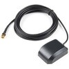
Description。Normal GPS antennas are optimized for the US based GPS reception which is great but with more and more modules capable of tracking additional constellations(termed GNSS receivers)you're going to need the right antenna! This exceptional GPS/GNSS antenna is designed for both GPS and GLONASS reception. When used in conjunction with the SparkFun GPS ground plate this antenna achieved excellent TTFF and SIV statistics for both GPS and GLONASS constellations. The magnetic mount allows it to be easily mounted to a metal base such as a ground plate or car roof. The antenna is terminated with a 3m cable and standard SMA connector.。We recommend this antenna for RTK use when combined with the ground plate. If you need Beidou reception and additional gain consider the GPS/GNSS embedded antenna.。Features。Dimensions:50x38x17mm。Weight:75g including 3m cable。Frequency Range:1575 - 1610MHz。GPS Center Frequency:1575.42MHz。GLONASS Center Frequency:1602MHz。LNA Voltage:3 to 5VDC。LNA Gain:28dB。LNA Current:10mA。Termination Connector:SMA。Impedance:50Ω。Right hand polarization。Cable Length:3 meter
アズワン品番67-0423-72
1個
¥3,398
税込¥3,738
33日以内出荷

We use these little buttons on everything! These Miniature Single Pole Single Throw switches have a good click to them and are breadboard friendly. Perfect as a tactile reset switch. These buttons are rated up to 50mA.
アズワン品番67-0452-50
1個
¥109
税込¥120
33日以内出荷

Description。The SparkFun moto:bit is a fully loaded "carrier" board for the micro:bit that, when combined with the micro:bit, provides you with a fully functional robotics platform. The moto:bit offers a simple, beginner-friendly robotics controller capable of operating a basic robotics chassis. Onboard each moto:bit are multiple I/O pins, as well as a vertical Qwiic connector, capable of hooking up servos, sensors and other circuits. At the flip of the switch you can get your micro:bit moving!。The moto:bit connects to the micro:bit via an updated SMD, edge connector at the top of the board, making setup easy. This creates a handy way to swap out micro:bits for programming, while still providing reliable connections to all of the different pins on the micro:bit. We have also included a basic barrel jack on the moto:bit that is capable of providing power to anything you connect to the carrier board.。The micro:bit is a pocket-sized computer that lets you get creative with digital technology. Between the micro:bit and our shield-like bit boards you can do almost anything while coding, customizing and controlling your micro:bit from almost anywhere! You can use your micro:bit for all sorts of unique creations, from robots to musical instruments and more. At half the size of a credit card, this versatile board has vast potential!。Note:The SparkFun moto:bit does。NOT。include a micro:bit board. The micro:bit will need to be purchased separately.。Get started with the moto:bit Guide。Features。More reliable Edge connector for easy use with the micro:bit。Full H-Bridge for control of two motors。Control servo motors。Vertical Qwiic Connector。I2C port for extending functionality。Power and battery management onboard for the micro:bit
アズワン品番67-0422-89
1個
¥6,798
税込¥7,478
33日以内出荷

Description。The SparkFun Pulse Oximeter and Heart Rate Sensor is an I2C based biometric sensor, utilizing two chips from Maxim Integrated:the MAX32664 Biometric Sensor Hub and the MAX30101 Pulse Oximetry and Heart Rate Module. While the latter does all the sensing, the former is an incredibly small and fast Cortex M4 processor that handles all of the algorithmic calculations, digital filtering, pressure/position compensation, advanced R-wave detection, and automatic gain control. We've provided a Qwiic connector to easily connect to the I2C data lines but you will also need to connect to two additional lines. This board is very small, measuring at 1in×0.5in(25.4mm×12.7mm), which means it will fit nicely on your finger without all the bulk.。The MAX30101 does all the sensing by utilizing its internal LEDs to bounce light off the arteries and arterioles in your finger's subcutaneous layer and sensing how much light is absorbed with its photodetectors. This is known as photoplethysmography. This data is passed onto and analyzed by the MAX32664 which applies its algorithms to determine heart rate and blood oxygen saturation(SpO2). SpO2 results are reported as the percentage of hemoglobin that is saturated with oxygen. It also provides useful information such as the sensor's confidence in its reporting as well as a handy finger detection data point. To get the most out of the sensor we've written an Arduino Library to make it easy to adjust all the possible configurations.。The SparkFun Qwiic connect system is an ecosystem of I2C sensors, actuators, shields and cables that make prototyping faster and less prone to error. All Qwiic-enabled boards use a common 1mm pitch, 4-pin JST connector. This reduces the amount of required PCB space, and polarized connections mean you can't hook it up wrong.。Get Started with the Pulse Oximeter and Heart Rate Monitor Hookup Guide。Features。SparkFun Pulse Oximeter and Heart Rate Sensor。MAX30101 and MAX32664 sensor and sensor hub。Qwiic connectors for power and I2C interface。I2C Address:0x55。MAX30101 - Pulse Oximeter and Heart-Rate Sensor。Heart-Rate Monitor and Pulse Oximeter Sensor in LED Reflective Solution。Integrated Cover Glass for Optimal, Robust Performance。Ultra-Low Power Operation for Mobile Devices。Fast Data Output Capability。Robust Motion Artifact Resilience。MAX32664 - Ultra-Low Power Biometric Sensor Hub。Biometric Sensor Hub Solution。Finger-Based Algorithms Measure Pulse Heart Rate and Pulse Blood Oxygenation Saturation(SpO2)。Both Raw and processed data are available。Basic Peripheral mix optimizes size and performance
アズワン品番67-0426-96
1個
¥9,298
税込¥10,228
33日以内出荷

。Description。The SparkFun Variable Load Kit is a quick-to-assemble board designed to allow users to draw a specific amount of current from a voltage input. This kit can be used to test stability of the power supply under various loads, battery lifetime, safety cutoffs and other design elements. The Variable Load Kit can test supplies of up to 30V at currents ranging from a few mA all the way up to 4A.。The Variable Load board is meant to work with one of two output modes:either using a console on a PC for feedback or using a 16x2 character LCD(found in the Hookup Accessories section below). In either case, the capacitive touch buttons on the front of the Variable Load PCB can be used to change the settings. There are four buttons:up arrow, down arrow, enter and back. The up and down arrow keys will adjust the current set point, the enter key turns the load on or off, and the back button resets the set point to zero. Additionally, there is an LED visible that will tell you whether the load is enabled or disabled at any given time.。For safety, please be sure that the total load power is limited to 15W because, even at that wattage, the heatsink will get hot to the touch.。Note:This kit will need to be assembled before use, so knowledge of soldering will be required. Also, the SparkFun Variable Load Kit does NOT include headers or an LCD to solder them to.。Get Started With the Variable Load Kit Guide
アズワン品番67-0424-10
1個
¥12,980
税込¥14,278
33日以内出荷

。Description。The SparkFun Wireless Joystick Kit provides an easy way to control your next XBee project. Before the wireless joystick, radio-controlled projects used hobby RC transmitters, the same ones used for RC cars, boats and planes. The problem with these transmitters is that many aren't customizable, and the ones that are tend to be too expensive for many of us. The Wireless Joystick Kit offers a custom wireless solution for those who want to control their project their own way.。Equipped with the increasingly popular SAMD21 onboard, all you need is to assemble the SparkFun Wireless Joystick into the configuration you want and add your own XBee and lithium ion battery into the provided sockets. The Wireless Joystick Kit can be assembled into a configuration that utilizes dual joysticks for better RC steering robots(like tanks)or a single joystick configuration with four 12mm momentary pushbuttons(a setup similar to what older game consoles used). We have provided a full Hookup Guide that gives assembly instructions, as well as a tank-steering motor controller tutorial to help get you started!。Please be aware that the SparkFun Wireless Joystick Kit is。NOT supported on Windows 7/8。due to a lack of support drivers for those specific OS's.。Note:This kit will need to be assembled before use, so a beginner's knowledge of soldering will be required. Additionally, in an effort to keep shipping rates down and make this kit available to people throughout the world without delay, there is no XBee or lithium ion battery included.。Get Started with the Wireless Joystick Kit Guide
アズワン品番67-0424-08
1個
¥10,980
税込¥12,078
33日以内出荷

Description。The SparkFun RTK Express Plus is an easy to use GNSS receiver for centimeter-level positioning. Perfect for surveying, autonomous vehicles, logging, and all types of post processing, this preprogrammed device can also be used for autonomous driving, navigation, asset tracking and any other application where there is a clear view of the sky. The RTK Express Plus adds an internal IMU to combine real-time GNSS tracking with advanced sensor fusion. The result is accurate positioning even when GNSS is lost in tunnels, parking garages, etc. Out of the box an RTK Express Plus can be used with a correction source to create an RTK system capable of 14mm horizontal positional accuracy. The built-in Bluetooth(R)connection via an ESP32 WROOM enables the user to use the RTK Express Plus with their choice of GIS application on a phone or tablet. The built in battery allows for over five hours of field use and is compatible with common USB battery banks.。We took all the lessons from the RTK Surveyor and built the RTK Express Plus. The RTK Express Plus is built upon the ZED-F9R u-blox receiver which uses the same F9 engine as all our RTK products but couples it with a built-in IMU. The embedded display allows for immediate feedback of horizontal positional accuracy, satellites in view, logging status, sensor fusion status, battery level, Bluetooth(R)MAC, etc. The rocker switches found on the original have been replaced by keypad buttons. We increased the battery to 1300mAh for a longer run time. The internal switches have been replaced by a digital mux allowing for some really exciting applications including event triangulation. More ESD protection was added to protect the RF path, and we even threw in an accelerometer for digital leveling in the field. Please note u-blox's sensor fusion algorithms are designed specifically for vehicles and will not aid in the accuracy of normal surveying.。This device can be used in two modes:GNSS Positioning(~30cm accuracy)。GNSS Positioning with RTK(1.4cm accuracy)。In Position mode the device receives L1/L2 signals from a user-provided antenna and the high-grade GNSS receiver provides lat/long and altitude with accuracies around 300mm. If enabled in automotive applications, the internal IMU augments the position information when GNSS reception is degraded.。In Positioning with RTK mode the device receives L1/L2 signals from the antenna and correction data from a base station. The correction data can be obtained from a cellular link to online correction sources or over a radio link to a RTK Surveyor/Express setup as a base station. If enabled in automotive applications, the internal IMU augments the position information when GNSS reception is degraded.。Two cables are provided with the RTK Express Plus allowing a user to plug in our easy to use Serial Telemetry Radios or their own radio link. If a local correction source is within 10km, a user can also use their phone to provide correction data over the Bluetooth(R)link(no external radio needed!).。Note:The SparkFun RTK Express Plus is just the enclosed device and does NOT include an antenna, serial telemetry radio, or associated mounting pieces. These items will need to be purchased separately from the Hookup Accessories below.。Get Started With the SparkFun RTK Express Guide。Features。GNSS Receiver:ZED-F9R。Concurrent reception of GPS, GLONASS, Galileo and BeiDou。Receives both L1C/A and L2C bands。Built-in IMU(triple axis accel, triple axis gyro)。Current:68mA - 130mA(varies with constellations and tracking state)。Time to First Fix:25s(cold), 2s(hot)。Max Navigation Rate:PVT(basic location over UBX binary protocol)- 25Hz。RTK - 20Hz。Raw - 25Hz。Horizontal Position Accuracy:2.5m without RTK。0.010m with RTK。Max Altitude:50km(31 miles)。Max Velocity:500m/s(1118mph)。Bluetooth(R)Transceiver:ESP32 WROOM。Xtensa(R)dual-core 32-bit LX6 microprocessor。Up to 240MHz clock frequency。16MB of flash storage。520kB internal SRAM。Integrated 802.11 BGN WiFi transceiver。Integrated dual-mode Bluetooth(R)(classic and BLE)。Hardware accelerated encryption(AES, SHA2, ECC, RSA-4096)。2.5 μA deep sleep current。Overall Device。Internal Battery:LiPo 1300mAh with 500mA charging。Radio Port:3.3V TTL Serial(57600bps RTCM TX/RX)。Data Port:3.3V TTL Serial(460800bps NMEA)。Embedded OLED Display for available satellites, data logging, and more.。Push button controls。Weight:162g(entire device including battery)。Dimensions:132mm×101mm×32mm(5.2in×3.9in×1.2in)。1x Qwiic Connector。1x microSD Socket for optional logging
アズワン品番67-0423-97
1個
¥149,800
税込¥164,780
33日以内出荷

Description。The SparkFun ProtoShield Kit lets you customize your own Arduino shield using whatever circuit you can come up with and then test it to make sure everything is working the way it should! The SparkFun ProtoShield Kit is based off the Arduino R3's footprint that allows you to easily incorporate it with favorite Arduino-based device.。One of our favorite features with this version of the ProtoShield Kit is the solderable-like breadboard prototyping area! Half of this area was designed with a breadboard in mind. On the underside of the shield you will be able to see open jumper pads between each through hole to make a connection like a breadboard. Once you add a component, simply add a solder jumper between holes to make a connection. For those that prefer the standard prototyping pads, we left the other side(near the BlueSMiRF and Serial UART ports)as is.。We have also moved the prototype testing components(those used to make sure your circuit works effectively)off of the "mainland" of the shield and onto a ProtoSnap styled, removable PCB. On this test area you will find soldering areas for the two yellow 3mm LEDs(as well as pins to control and power them), two 330 Ohm resistors, a 10K Ohm resistor, and a pushbutton.。Note:。Since this product is a kit, assembly and a basic knowledge of soldering will be required. The SparkFun ProtoShield Kit does not come pre-assembled.。Get Started With the SparkFun ProtoShield Kit Guide。Features。Arduino R3 Footprint。Soldering Kit。Solderable-Like Breadboard。BlueSMiRF or Comparable 6-pin Pins。Detachable Test Area
アズワン品番67-0422-25
1個
¥3,298
税込¥3,628
33日以内出荷

Description。The SparkFun weather:bit is a fully loaded "carrier" board for the micro:bit that, when combined with the micro:bit, provides you with a fully functional weather station. With the weather:bit you will have access to barometric pressure, relative humidity and temperature readings. There are also connections on this carrier board to optional sensors such as wind speed, direction, rain gauge and soil readings! In this version we have also added a vertical Qwiic connector. The micro:bit has a lot of features and a lot of potential for weather data collection.。The weather:bit connects to the micro:bit via an edge connector at the top of the board, making setup easy. This creates a handy way to swap out micro:bits for programming, while still providing reliable connections to all of the different pins on the micro:bit. We have also included serial and I2C headers on the weather:bit for optimized connectivity if you so choose.。The micro:bit is a pocket-sized computer that lets you get creative with digital technology. Between the micro:bit and our shield-like bit boards you can do almost anything while coding, customizing and controlling your micro:bit from almost anywhere! You can use your micro:bit for all sorts of unique creations, from robots to musical instruments and more. At half the size of a credit card, this versatile board has vast potential!。Note:The SparkFun weather:bit does。NOT。include a micro:bit board. The micro:bit will need to be purchased separately.。Get started with the weather:bit Guide。Features。Onboard temperature, humidity, and pressure sensor。Connectors(PTH and screw terminal)for soil moisture and soil temperature。Connectors(RJ11)for wind speed, direction and rainfall gauges。Edge connector for easy micro:bit integration。Vertical Qwiic connector。Headers for Serial and I2C communication
アズワン品番67-0422-94
1個
¥4,898
税込¥5,388
33日以内出荷

Description。Do you own micro:bit or micro:bit Go Bundle and want to expand your skills with the new microcontroller? You are in luck! The SparkFun Inventor's Kit Bridge Pack for micro:bit was designed to provide you with an easy way to transform your m:b into full fledged learning kit! Each Bridge Pack includes all of the parts found in the SIK for micro:bit that aren't included with the Go Bundle. With the SIK Bridge Pack for micro:bit you will be able to complete circuits that will teach you how to read sensors, move motors, build Bluetooth(R)devices and more.。The micro:bit is pocket-sized computer that lets you get creative with digital technology. Between the micro:bit and our shield-like bit boards you can do almost anything while coding, customizing and controlling your micro:bit from almost anywhere! You can use your micro:bit for all sorts of unique creations, from robots to musical instruments and more. At half the size of credit card, this versatile board has vast potential!。Note:The Bridge Pack is NOT full SparkFun Inventor's Kit and only includes the parts to complement micro:bit Go Bundle or standalone board. That also means that this kit does。not。include micro:bit, which will need to be purchased separately.。Get started with the micro:bit SIK Experiment Guide。Examples。Circuit 0:Hello, micro:bit!。Circuit 1:Blinking an LED。Circuit 2:Reading Potentiometer。Circuit 3:Reading Photoresistor。Circuit 4:Driving an RGB LED。Circuit 5:Reading an SPDT Switch。Circuit 6:Reading Button Press。Circuit 7:Reading the Temperature Sensor。Circuit 8:Using Servo Motor。Circuit 9:Using Buzzer。Circuit 10:Using the Accelerometer。Circuit 11:Using the Compass
アズワン品番67-0424-21
1個
¥12,980
税込¥14,278
33日以内出荷

。Description。The HM01B0 from Himax Imaging is an ultra low power CMOS Monochrome Image Sensor that enables the integration of an "Always On" camera for computer vision applications such as gestures, intelligent ambient light and proximity sensing, tracking and object identification. The sensor allows the sensor to consume very low power of <2mW at QVGA 30FPS. This low power consumption and vision applications camera comes with a ribbon cable that mates to the camera connector populated on the following products:MicroMod Machine Learning Carrier Board。Artemis Development Kit。Edge Development Board - Apollo3 Blue。The HM01B0 contains 320×320 pixel resolution and supports a 320×240 window mode which can be readout at a maximum frame rate of 60FPS, and a 2×2 monochrome binning mode with a maximum frame rate of 120FPS. The video data is transferred over a configurable 1bit, 4bit or 8bit interface with support for frame and line synchronization. The sensor integrates black level calibration circuit, automatic exposure and gain control loop, self-oscillator and motion detection circuit with interrupt output to reduce host computation and commands to the sensor to optimize the system power consumption.。Features。Image Sensor。Ultra Low Power Image Sensor(ULPIS)designed for Always On vision devices and applications。High sensitivity 3.6μ BrightSenseTM pixel technology。320×320 active pixel resolution with support for QVGA window, vertical flip and horizontal mirror readout。Programmable black level calibration target, frame size, frame rate, exposure, analog gain(up to 8x)and digital gain(up to 4x)。Automatic exposure and gain control loop with support for 50 / 60Hz flicker avoidance。Flexible 1bit, 4bit and 8bit video data interface with video frame and line sync。Motion Detection circuit with programmable ROI and detection threshold with digital output to serve as an interrupt。On-chip self oscillator。I2C 2-wire serial interface for register access。High CRA for low profile module design。Sensor Parameters。Active Pixel Array 320×320。Pixel Size 3.6 μm×3.6 μm。Full Image Area 1152 μm×1152 μm。Diagonal(Optical Format)1.63 mm(1/11″)。Scan Mode:Progressive。Shutter Type:Electronic Rolling Shutter。Frame Rate MAX 51 fps @ 320×320, 60 fps @ 320×240(QVGA)。CRA(maximum)30℃。Sensor Specifications。Supply Voltage:Analog - 2.8 V, Digital - 1.5V(Internal LDO:1.5V - 2.8V), I/O - 1.5 - 2.8V。Input Reference Clock:3 - 50 MHz。Serial Interface(I2C):2-wire, 400 KHz max.。Video Data Interface:1b, 4b, 8b with frame / line SYNC。Output Clock Rate MAX:50 MHz for 1bit, 12.5 MHz for 4bit, 6.25 MHz for 8bit。Est. Power Consumption(include IO with 5pF load):QVGA 60FPS(Typical)<4 mW。QVGA 30FPS(Typical)<2 mW
アズワン品番67-0427-08
1個
¥2,998
税込¥3,298
33日以内出荷

Description。The SparkFun RTK Surveyor is an easy to use GNSS receiver for centimeter-level positioning. Perfect for surveying, this preprogrammed device can also be used for autonomous driving, navigation, asset tracking and any other application where there is a clear view of the sky. The RTK Surveyor can also be used as a base station. With the flick of a switch, two RTK Surveyors can be used to create an RTK system capable of 14mm horizontal positional accuracy. The built-in Bluetooth(R)connection via an ESP32 WROOM enables the user to use the RTK Surveyor with their choice of GIS application on a phone or tablet. The built in battery allows field use for up to four hours and is compatible with common USB battery banks.。This device can be used in four modes:GNSS Positioning(~30cm accuracy)。GNSS Positioning with RTK(1.4cm accuracy)。GNSS Base Station。GNSS Base Station NTRIP Server。In Position mode the device receives L1/L2 signals from a user-provided antenna and the high-grade GNSS receiver provides lat/long and altitude with accuracies around 300mm.。In Positioning with RTK mode the device receives L1/L2 signals from the antenna and correction data from a base station. The correction data can be obtained from a cellular link to online correction sources or over a radio link to a 2nd RTK Surveyor setup as a base station.。In Base Station mode the device is mounted to a temporary position(like a tripod)and begins transmitting correction data over a radio or internet connection. A base is often used in conjunction with a second unit set to 'Positioning with RTK' to obtain the 14mm relative accuracy.。In Base Station NTRIP Server mode the device is mounted to a semi or permanently fixed position(like a roof)and connects over WiFi to transmit the correction data to a NTRIP caster so that any rover can access the correction data over a cellular or internet connection. This type of base is a very easy way to setup a very precise absolute correction source.。Two cables are provided with the RTK Surveyor allowing a user to plug on our easy to use Serial Telemetry Radios or their own radio link. If a local correction source is within 10km, a user can also use their phone to provide correction data over the Bluetooth(R)link(no external radio needed!).。Note:The SparkFun RTK Surveyor is just the enclosed device and does NOT include an antenna, serial telemetry radio, or associated mounting pieces. These items will need to be purchased separately from the Hookup Accessories below.。Get Started With the SparkFun RTK Surveyor Guide。Features。GNSS Receiver:ZED-F9P。Concurrent reception of GPS, GLONASS, Galileo and BeiDou。Receives both L1C/A and L2C bands。Current:68mA - 130mA(varies with constellations and tracking state)。Time to First Fix:25s(cold), 2s(hot)。Max Navigation Rate:PVT(basic location over UBX binary protocol)- 25Hz。RTK - 20Hz。Raw - 25Hz。Horizontal Position Accuracy:2.5m without RTK。0.010m with RTK。Max Altitude:50km(31 miles)。Max Velocity:500m/s(1118mph)。Bluetooth(R)Transceiver:ESP32 WROOM。Xtensa(R)dual-core 32-bit LX6 microprocessor。Up to 240MHz clock frequency。16MB of flash storage。520kB internal SRAM。Integrated 802.11 BGN WiFi transceiver。Integrated dual-mode Bluetooth(R)(classic and BLE)。Hardware accelerated encryption(AES, SHA2, ECC, RSA-4096)。2.5 μA deep sleep current。Overall Device。Internal Battery:LiPo 1000mAh with 500mA charging。Radio Port:3.3V TTL Serial(57600bps RTCM TX/RX)。Data Port:3.3V TTL Serial(115200bps NMEA)。Weight:132g(entire device including battery)。Dimensions:118mm×79mm×30mm(4.7in×3.1in×1.2in)。1x Qwiic Connector。1x microSD Socket for optional logging。Changes:This version(which replaces SPX-17369)uses a reinforced edge mount SMA connector for better resiliency when a fixed 'stub' antenna is used.
アズワン品番67-0423-95
1個
¥99,980
税込¥109,978
33日以内出荷

Description。The SparkFun Artemis Development Kit is the latest board to be released around the SparkFun Artemis Module and it allows access to more software development features than previous Artemis based boards. This Kit includes the SparkFun Artemis DK board as well as the accessories(Himax camera USB-C cable)needed to get started right away. Recommended software used to program the Artemis DK are the Arduino IDE, Arm(R)Mbed(TM)OS(Studio and CLI), and AmbiqSDK. An updated USB interface(MKL26Z128VFM4 Arm(R)Cortex(R)-M0+ MCU, from NXP)allows the Artemis Dev Kit to act as:Mass Storage Device(MSD):Used to provide drag and drop programming to the Artemis Module.。Human Interface Device(HID):Used for the debugging interface to the Artemis Module.。Communication Port(COM):Used to provide a serial communication UART between the Artemis and the USB connection(PC).。The Artemis Module provides a Cortex(R)-M4F with BLE 5.0 running at 48MHz with an available 96MHz turbo mode and power as low as 6uA per MHz(less than 5mW). The SparkFun Artemis Module is fully FCC/IC/CE certified with 1M flash and 384k RAM you'll have plenty of room for your code. The flexibility of the Artemis module starts with our Arduino core. You can program and use the Artemis module just like you would an Uno or any other Arduino. Additional functionality stems from the ability of the Artemis Dev kit to run RTOS such as the Arm Mbed OS, or the AmbiqSDK.。Attached to the。"Qwiic"。I2C bus, we've added a LIS2DH12TR MEMS accelerometer(for things like gesture recogntion), a digital MEMS microphone, and an edge camera connector for the Himax CMOS imaging camera to experiment with always-on voice commands, and image recognition with TensorFlow and machine learning. All of the Artemis Development Kit pins are broken out to 0.1" spaced female headers(i.e. connectors). There are also two rows of breakout pins with 0.1" pitch spacing for headers; and a 0.08" pitch spacing to clip on IC-hooks, used by most logic analyzers. Additionally the Silk on the back of the Artemis DK acts as a chart to show pins by functionality(peripherals, ADC, PWM, UART0, UART1)and act as an aid while developing software. The board is powered programmed via USB-C, and includes a Qwiic connector to make I2C easy and is fully compatible with SparkFun's Arduino core to be programmed under the Arduino IDE.。Get Started With the SparkFun Artemis Development Kit Guide。Features。Artemis Dev Kit。Compatible with Arduino, Mbed(TM)OS, and AmbiqSDK Development Programs。Power:5V Provided Through the USB-C Connector。1.8V, 3.3V, and 5V Available on Power Header。Interface Chip(MKL26Z128VFM4 ARM(R)Cortex(R)-M0+ MCU):Drag and Drop Programming。SWD Interface。JTAG Programming PTH。Artemis Module:Apollo3 ARM(R)Cortex(R)-M4F MCU。BLE 5.0 with FCC Certification。24 Breakout I/O Pins。Eight 14-bit ADC Pins。Eighteen 16-bit PWM Pins。Two Independent UART Ports。Three Peripheral I2C/SPI Buses。JTAG Programming PTH。Sensors:3-axis Accelerometer(LIS2DH12)。PDM Microphone(SPH0641LM4H-1)。Camera Connector(for the Himax HM01B0 Camera)。Qwiic Connector。On Primary I2C Bus。Himax HM01B0 Camera。Image Sensor。Ultra Low Power Image Sensor(ULPIS)designed for Always On vision devices and applications。High sensitivity 3.6μ BrightSenseTM pixel technology。320×320 active pixel resolution with support for QVGA window, vertical flip and horizontal mirror readout。Programmable black level calibration target, frame size, frame rate, exposure, analog gain(up to 8x)and digital gain(up to 4x)。Automatic exposure and gain control loop with support for 50 / 60Hz flicker avoidance。Flexible 1bit, 4bit and 8bit video data interface with video frame and line sync。Motion Detection circuit with programmable ROI and detection threshold with digital output to serve as an interrupt。On-chip self oscillator。I2C 2-wire serial interface for register access。High CRA for low profile module design。Sensor Parameters。Active Pixel Array 320×320。Pixel Size 3.6 μm×3.6 μm。Full Image Area 1152 μm×1152 μm。Diagonal(Optical Format)1.63 mm(1/11″)。Color Filter Array Monochrome and Bayer。Scan Mode:Progressive。Shutter Type:Electronic Rolling Shutter。Frame Rate MAX 51 fps @ 320×320, 60 fps @ 320×240(QVGA)。CRA(maximum)30℃。Sensor Specifications。Supply Voltage:Analog - 2.8 V, Digital - 1.5V(Internal LDO:1.5V - 2.8V), I/O - 1.5 - 2.8V。Input Reference Clock:3 - 50 MHz。Serial Interface(I2C):2-wire, 400 KHz max.。Video Data Interface:1b, 4b, 8b with frame / line SYNC。Output Clock Rate MAX:50 MHz for 1bit, 12.5 MHz for 4bit, 6.25 MHz for 8bit。Est. Power Consumption(include IO with 5pF load):QVGA 60FPS(Typical)<4 mW。QVGA 30FPS(Typical)<2 mW
アズワン品番67-0424-56
1個
¥12,980
税込¥14,278
33日以内出荷
関連キーワード