


絞り込み
ブランド
- SPARKFUN
- エクスナレッジ(10)
- ダイテック(1)
- 四電工(12)
- HP(日本ヒューレット・パッカード)(15)
- エレコム(36)
- 共立出版(2)
- 日刊工業新聞社(4)
- フォトロン(8)
- メディアカバーマーケット(112)
- StarTech.com(73)
- 中川製作所(20)
- ATEN(13)
- EPSON(12)
- ARMOR-X(12)
- GATOR Case(12)
- BUFFALO(バッファロー)(11)
- NEC(10)
- brother(ブラザー)(10)
- ブランドをもっと見る
商品レビュー
- 以上(0)
- 以上(0)
- 以上(0)
- 以上(0)
価格
- 1,500円以下(49)
- 1,500-10,000円(85)
- 10,000-50,000円(49)
- 50,000-100,000円(4)
- 100,000円以上(3)
価格で絞り込む
出荷目安
- 当日
- 翌日以内
- 翌々日以内
- 3日以内
- 4日以内
当日・翌日以内・翌々日以内・3日以内・4日以内
その他
- 取扱い終了商品を除く
- 個人購入不可商品を除く
 Zrn Coated Flat Cutter - 0.25" Diameter, #201Z 2 PackSPARKFUN
¥16,980税込¥18,678
1個
33日以内出荷
DescriptionThis is a two pack of Zrn coated flat mills from Carbide 3D that are perfect for fabricating with aluminum. Each mill in this pack features a cutting and shank diameter of 0.25 inches and a cutting length of 0.75 inches. These cutters really are great for precision 3D machining and fabrication.These cutters are coated with Zirconium Nitride(Zrn). This is a specialty coating which makes it most suitable for temperature sensative materials. ZrN had excellent corrosion-resistance, lubricity and hardness to suit many applications. This coating has a unique ability to reduce the build-up edge on cutting tools which results in a better surface finish. ZrN works well for machining Titanium and Aluminum Alloys, Nickel, Brass, Copper, Cast Iron and Zinc. Each cutter is made of solid carbide to ensure long lasting use.FeaturesCutting Diameter:0.25"Cutting Length:0.75"Shank Diameter:0.25"3 Flute, center cutting2.5" Overall Length
アズワン品番67-0428-49
 USB to Micro-B AdapterSPARKFUN
¥469税込¥516
1個
33日以内出荷
DescriptionIt's tiny, it's handy, and it can give your normal USB-equipped device a micro-B connector! With the USB to Micro-B Adapter you can make a flash drive connect to your tablet, connect a keyboard to your phone in order to text with ease, attach a Bluetooth(R)dongle to your RPi Zero, and more! Since this adapter is super small, it is very easy to transport anywhere you might need it --- making it extremely convenient to have in a pinch.Installation of the USB to Micro-B Adapter is easy; simply slide it into a USB A connector, and you will instantly make that device micro-B capable!
アズワン品番67-0421-07
 SparkFun Raspberry Pi 4 Hardware Starter Kit - 4GBSPARKFUN
¥55,980税込¥61,578
1個
33日以内出荷
DescriptionThe Raspberry Pi 4 Hardware Starter Kit provides a solid set of parts and instruction for working with the Raspberry Pi 4 in a more hardware-centric manner. While the Raspberry Pi isn't typically considered a go-to for hardware projects, its I/O pins hold a lot of benefits that you can use for a variety of applications. This kit covers the basics like using LEDs, and Buttons while providing a solid set of parts for working with any other hardware I/O and the 40-pin header. In addition, we've included all the parts needed for getting the Raspberry Pi 4 up and running whether it's on its own, or using a monitor(not included). The new 64GB MicroSD cards keep read/write commands running super fast, too.Most of the contents of the kit rely on the use of the 2x20, 40-pin header, so we've included a special extender to allow you to plug in the ribbon cable while using the provided heatsink case. We've also included a Qwiic Shim for easily working with I2C based Qwiic boards with the Pi. No soldering is required for this kit!Note:This variation includes the 4GB RAM option for the Raspberry Pi 4.Get Started with the Raspberry Pi 4 Model B Guide
アズワン品番67-0424-46
 SparkFun Qwiic Thermocouple Amplifier - MCP9600 Screw TerminalsSPARKFUN
¥7,998税込¥8,798
1個
予約販売
DescriptionThe MCP9600 Breakout is a high accuracy Thermocouple Amplifier equipped with an I2C interface, accessed over our Qwiic system. Inside the chip are two temperature sensors, one for the thermocouple itself(the hot junction)and one for the chip itself(the cold junction). As a result, the MCP9600 can read both the ambient temperature and the temperature of whatever you're trying to measure! The MCP9600 can do both with a resolution of 0.0625℃, and an accuracy of ±1.5℃(worst-case). The MCP9600 Thermocouple Amplifier is one of our many Qwiic compatible boards! Simply plug and go. No soldering, no figuring out which is SDA or SCL, and no voltage regulation or translation required!This version of the board comes equipped with screw terminals to allow for your own Thermocouple's wiring to be hooked up with the turn of a screw. This makes it perfect for a variety of applications, from measuring the temperature of your Crock-Pot to making sure your backyard induction furnace is up to temperature.In addition, the MCP9600 has four on-board temperature alerts that you can configure! Instead of constantly polling the sensor over I2C, you can set a temperature limit to trigger an interrupt when the temperature reaches a certain value. This frees up your microcontroller and your I2C bus to do more important things. It's also possible to put the MCP9600 into alternate operation modes in order to save power. The sensor supports a burst mode, where it will take a specified number of samples, return the results, and then go to sleep. This low-power mode makes the MCP9600 perfect for portable applications!We've written an Arduino library to help you get started quickly. You can download the library through the Arduino library manager by searching 'SparkFun MCP9600' or you can get the GitHub repo as a .zip file and install the library from there.The SparkFun Qwiic Connect System is an ecosystem of I2C sensors, actuators, shields and cables that make prototyping faster and less prone to error. All Qwiic-enabled boards use a common 1mm pitch, 4-pin JST connector. This reduces the amount of required PCB space, and polarized connections mean you can't hook it up wrong.Get Started with the Qwiic Thermocouple AmplifierFeaturesTemperature Range of -200℃ to 1350℃Four Onboard Temperature AlertsResolution of 0.0625℃Screw Terminal ConnectorADDR Jumper for variable I2C Addresses(default address of 0x60)2x Qwiic Connectors
アズワン品番67-0427-15
 SparkFun Qwiic HAT for Raspberry PiSPARKFUN
¥1,798税込¥1,978
1個
33日以内出荷
DescriptionThe SparkFun Qwiic HAT for Raspberry Pi is the quickest and easiest way to enter into SparkFun's Qwiic ecosystem while still using that Raspberry Pi that you've come to know and love. The Qwiic HAT connects the I2C bus(GND, 3.3V, SDA and SCL)on your Raspberry Pi to an array of Qwiic connectors on the HAT. Since the Qwiic system allows for daisy chaining boards with different addresses, you can stack as many sensors as you'd like to create a tower of sensing power!The Qwiic Pi HAT has four Qwiic connect ports, all on the same I2C bus. In addition, many of the useful GPIO pins on the Raspberry Pi are broken out. This HAT is compatible with any Raspberry Pi that utilizes the standard 2x20 GPIO header. It has been designed to sit to the side of the Pi, allowing it to work conveniently with a Pi Tin enclosure to connect boards to the Qwiic ports.Note:There is a small silk error that has reversed the SDA and SCL. This is simply a cosmetic mix-up and will not impact any function with this board.The SparkFun Qwiic Connect System is an ecosystem of I2C sensors, actuators, shields and cables that make prototyping faster and less prone to error. All Qwiic-enabled boards use a common 1mm pitch, 4-pin JST connector. This reduces the amount of required PCB space, and polarized connections mean you can't hook it up wrong.Get Started with the SparkFun Qwiic Pi HAT GuideFeatures4x Qwiic Connection PortsSelect GPIO Pins Broken OutPi Tin Compatibility
アズワン品番67-0422-50
 SparkFun Qwiic Dual Solid State RelaySPARKFUN
¥39,980税込¥43,978
1個
33日以内出荷
DescriptionThe SparkFun Qwiic Dual Solid State Relay is a power delivery board that allows users to switch two AC loads from a low power microcontroller using the SparkFun Qwiic connect system. The board features two 25A/250VAC solid state relays that utilize the Zero Cross Trigger method so you can toggle two loads on a 60Hz AC carrier signal on and off up to 120 times per second!An ATTiny84 acts as the "brain" of the SparkFun Qwiic Dual Solid Relay to accept I2C commands to toggle the two relays as well as a few other special commands. The I2C address of the ATtiny84A is software configurable so, if you have a seriously big power project in mind, you could daisy chain over 100 Qwiic Dual Solid State Relays.Messing with such high voltage is dangerous! We've included many safety precautions onto the PCB including ground isolation between the relay and other circuitry and a milled out area isolating each side of AC. However, with all the safety precautions included with the SparkFun Qwiic Dual Solid State Relay, this is still a power accessory for users who are experienced around, and knowledgeable about high AC voltage. If you're not comfortable with handling AC voltage in this way, you may want to check out the IoT Power Relay instead.Note:The relays are rated for a max of 25A with forced air cooling. If you do not have forced air cooling, 10A max through the relays is recommended.The SparkFun Qwiic connect system is an ecosystem of I2C sensors, actuators, shields and cables that make prototyping faster and less prone to error. All Qwiic-enabled boards use a common 1mm pitch, 4-pin JST connector. This reduces the amount of required PCB space, and polarized connections mean you can't hook it up wrong.Get Started with the SparkFun Qwiic Dual Solid State Relay GuideFeaturesOperating Voltage:2.5-3.6V(3.3V recommended)I2C Address:0x0A(Default)0x0B(Alternate via jumper select)Load Voltage Range:12-280VACMax Current(Through Relay):25A(240VAC with forced air cooling)Zero Cross TriggerNormally Open Circuit Only2x Qwiic Connector
アズワン品番67-0421-58
 SparkFun OpenScaleSPARKFUN
¥10,980税込¥12,078
1個
33日以内出荷
DescriptionThe SparkFun OpenScale is a simple-to-use, open source solution for measuring weight and temperature. It has the ability to read multiple types of load cells and offers a simple-to-use serial menu to configure calibration value, sample rate, time stamp and units of precision.Simply attach a four-wire or five-wire load cell of any capacity, plug the OpenScale into a USB port, open a terminal window at 9,600bps, and you'll immediately see mass readings. The SparkFun OpenScale will enable you to turn a load cell or four load sensors in a Wheatstone bridge configuration into the DIY weigh scale for your application.The OpenScale was designed for projects and applications where the load was static(like the beehive in front of SparkFun HQ)or where constant readings are needed without user intervention(for example, on a conveyor belt system). A load cell with an equipped OpenScale can remain in place for months without needing user interaction!On board the SparkFun OpenScale is the ATmega328P microcontroller, for addressing your communications needs and transferring your data to a serial terminal or to a data logger such as the OpenLog, an FT231 with mini USB, for USB to serial connection; the HX711, a 24-bit ADC for weigh scales; and the TMP102, for recording the ambient temperature of your system. The OpenScale communicates at a TTL level of 9,600bps 8-N-1 by default and possesses a baud rate configurable from 1,200bps to 1,000,000bps.Get Started with the OpenScale GuideFeaturesOperating Voltage:5VOperating Ampage:80-100mAPower Cycling above 500msSelectable 10SPS or 80SPS Output Data RateLocal External Temperature SensorsFixed Adjustable Gain
アズワン品番67-0426-48
 SparkFun MP3 Player ShieldSPARKFUN
¥10,980税込¥12,078
1個
予約販売
DescriptionThe SparkFun MP3 Player Shield is an awesome MP3 decoder with the capabilities of storing music files onto a run-of-the-mill microSD card, thus giving you the ability toadd music or sound effects to any project. With this board you can pull MP3 files from an microSD card and play them using only one shield, effectively turning any Arduino into a fully functional stand-alone MP3 player! The MP3 Shield utilizes the VS1053B MP3 audio decoder IC to decode audio files. The VS1053 is also capable of decoding Ogg Vorbis/MP3/AAC/WMA/MIDI audio and encoding IMA ADPCM and user-loadable Ogg Vorbis.The VS1053 receives its input bitstream through a serial input bus(SPI). After the stream has been decoded by the IC, the audio is sent out to both a 3.5mm stereo headphone jack, as well as a 2-pin 0.1" pitch header.This shield comes populated with all components as shown in the images and schematic; but it does not come with headers installed. We recommend the Arduino R3 Stackable Header Kit.Features3.5mm audio out jack0.1" spaced header for speaker outmicroSD card slot
アズワン品番67-0422-08
 SparkFun MicroMod ATP Carrier BoardSPARKFUN
¥4,398税込¥4,838
1個
33日以内出荷
DescriptionAccess all the pins(i.e. ATP)of the MicroMod Processor Boards with the SparkFun MicroMod ATP Carrier Board! This board breaks out the MicroMod Processor Board's pins on the M.2 connector to 0.1" spaced female headers and PTH pads on the edge of the board. This Carrier Board is great if you're interested in testing out different MicroMod Processor Boards for your application.A modern USB-C connector makes programming easy. In addition to the pins broken out, two separate Qwiic-enabled I2C ports allow you to easily daisy chain Qwiic-enabled devices. We've exposed the SWD pins for more advanced users who prefer to use the power and speed of professional tools. A USB-A connector is provided for Processor Boards that have USB Host support. A backup battery is provided for processor boards with RTC. If you need a "lot" of GPIO with a simple-to-program, ready for market module, the ATP is the fix you need. We've even added a convenient jumper to measure the current consumption for low power testing.MicroMod is a modular interface ecosystem that connects a microcontroller "processor board" to various "carrier board" peripherals. Utilizing the M.2 standard, the MicroMod standard is designed to easily swap out processors on the fly. Pair a specialized carrier board for the project you need with your choice of compatible processor!Get Started with the MicroMod ATP Carrier Board GuideFeaturesM.2 ConnectorOperating Voltage Range~3.3V to 6.0V(via VIN to AP7361C 3.3V Voltage Regulator)3.3V(via 3V3)Ports [1]1x USB type C1x USB type A Host2x Qwiic Enabled I2C1x CAN1x I2S2x SPI2x UARTs2x Dedicated Analog Pins2x Dedicated PWM Pins2x Dedicated Digital Pins12x General Purpose Input Output Pins1x SWD 2x5 header1mAh battery backup for RTCButtonsResetBootLEDsPower3.3VPhillips #0 M2.5x3mm screw included[1] Note:Depending on the design of the Processor Board, not all the pins may be accessible.
アズワン品番67-0423-18
 SparkFun MicroMod Artemis ProcessorSPARKFUN
¥5,598税込¥6,158
1個
33日以内出荷
DescriptionLeveraging the ultra powerful Artemis Module, the SparkFun MicroMod Artemis Processor is the brain board of your dreams. With a Cortex-M4F with BLE 5.0 running up to 96MHz and with as low power as 6uA per MHz(less than 5mW), the M.2 MicroMod connector allows you to plug in a MicroMod Carrier Board with any number of peripherals. Let's have a look at what this processor board has to offer! If you need Machine Learning capabilities, Bluetooth, I2C functionality to connect to all our amazing Qwiic boards, and more the Artemis Processor is the perfect choice for your MicroMod Carrier Board.At the heart of SparkFun's Artemis Module is Ambiq Micro's Apollo3 processor, whose ultra-efficient ARM Cortex-M4F processor is spec'd to run TensorFlow Lite using only 6uA/MHz. We've routed two I2C buses, eight GPIO, dedicated digital, analog, and PWM pins, multiple SPI as well as QuadSPI, and Bluetooth to boot. You really can't go wrong with this processor. Grab one today, pick up a compatible carrier board, and get hacking!MicroMod is a modular interface ecosystem that connects a microcontroller "processor board" to various "carrier board" peripherals. Utilizing the M.2 standard, the MicroMod standard is designed to easily swap out processors on the fly. Pair a specialized carrier board for the project you need with your choice of compatible processor!Get Started with the MicroMod Artemis Processor GuideFeaturesArtemis General Features1M Flash / 384k RAM48MHz / 96MHz turbo available6uA/MHz(operates less than 5mW at full operation)48 GPIO - all interrupt capable31 PWM channelsBuilt in BLE radio and antenna10 ADC channels with 14-bit precision with up to 2.67 million samples per second effective continuous, multi-slot sampling rate2 channel differential ADC2 UARTs6 I2C buses6 SPI buses2/4/8-bit SPI busPDM interfaceI2S InterfaceSecure 'Smart Card' interfaceFCC/IC/CE Certified(ID Number 2ASW8-ART3MIS)Specific Peripherals made available on MicroMod Artemis:1x USB dedicated for programming and debug1x UART with flow control2x I2C1x SPI1x Quad-SPI8x Fast GPIO2x Digital Pins2x Analog Pins2x PWM1x Differential ADC pairStatus LEDVIN Level ADCAdditional peripherals are available but are shared on dedicated MicroMod pins.
アズワン品番67-0423-05
 SparkFun Line Follower ArraySPARKFUN
¥11,980税込¥13,178
1個
予約販売
DescriptionThe SparkFun Line Follower Array is a long board consisting of eight IR sensors that have been configured to read as digital bits! We have designed the SparkFun Line Follower Arrays to follow a dark line of about 3/4 inch width or smaller(spray paint or electrical tape)on a light background. Each array features visible LEDs that point upward when the board is attached(properly)so you can see what the robot sees, brightness control right on the board, and an I2C interface for reading and power control. Here at SparkFun, the RedBot Shadow Chassis was used as a test platform but really this was designed as an add-on for almost any bot.The line follower functions by taking an 8-bit reading of reflectance for use with following lines or reading dark/light patterns and can see from about 1/4 to 3/4 inches away. The IR brightness control and indicator can be adjusted with the on-board potentiometer and is capable of showing you the strength of the IR LEDs. Illumination can be turned on and off with software to conserve power, or left on all the time for faster readings. The SparkFun Line Follower Array requires 5V of power with a supply current range of 25-185mA with strobing disabled and 16-160mA with it enabled. Additionally we have added six mounting holes to the line follower with the two inner holes designed to fit our Shadow Chassis while the other four are general purpose.Note:As you know our Sun emits quite a bit of infrared light, making the SparkFun Line Follower Array much less effective in direct sunlight. Plan your projects accordingly!Features8 sensor eyes(QRE1113, like in our line sensor breakout)I2C interfaceAdjust IR brightness on the fly with a knobSwitch IR on and off with softwareSwitch visual indicators on and off with softwareInvert dark/light sight with softwareBased on the SX1509 I/O expander
アズワン品番67-0426-55
 SparkFun GPS Breakout - NEO-M9N, SMA QwiicSPARKFUN
¥19,980税込¥21,978
1個
33日以内出荷
DescriptionThe SparkFun NEO-M9N GPS Breakout is a high quality GPS board with equally impressive configuration options including SMA. The NEO-M9N module is a 92-channel u-blox M9 engine GNSS receiver, meaning it can receive signals from the GPS, GLONASS, Galileo, and BeiDou constellations with ~1.5 meter accuracy. This breakout supports concurrent reception of four GNSS. This maximizes position accuracy in challenging conditions increasing, precision and decreases lock time; and thanks to the onboard rechargeable battery, you'll have backup power enabling the GPS to get a hot lock within seconds! Additionally, this u-blox receiver supports I2C(u-blox calls this Display Data Channel)which makes it perfect for the Qwiic compatibility so we don't have to use up our precious UART ports. Utilizing our handy Qwiic system, no soldering is required to connect it to the rest of your system. However, we still have broken out 0.1"-spaced pins in case you prefer to use a breadboard.The NEO-M9N module detects jamming and spoofing events and can report them to the host, so that the system can react to such events. A SAW(Surface Acoustic Wave)filter combined with an LNA(Low Noise Amplifier)in the RF path is integrated into the NEO-M9N module which allows normal operation even under strong RF interferences.U-blox based GPS products are configurable using the popular, but dense, windows program called u-center. Plenty of different functions can be configured on the NEO-M9N:baud rates, update rates, geofencing, spoofing detection, external interrupts, SBAS/D-GPS, etc. All of this can be done within the SparkFun Arduino Library!The SparkFun NEO-M9N GPS Breakout is also equipped with an on-board rechargeable battery that provides power to the RTC on the NEO-M9N. This reduces the time-to-first fix from a cold start(~24s)to a hot start(~2s). The battery will maintain RTC and GNSS orbit data without being connected to power for plenty of time.This product requires an antenna:Be sure to check out the related products/hookup accessories and pick a suitable SMA antenna for your project.The SparkFun Qwiic Connect System is an ecosystem of I2C sensors, actuators, shields and cables that make prototyping faster and less prone to error. All Qwiic-enabled boards use a common 1mm pitch, 4-pin JST connector. This reduces the amount of required PCB space, and polarized connections mean you can't hook it up wrong.The NEO-M9N GPS Breakout can also be automatically detected, scanned, configured, and logged using the OpenLog Artemis datalogger system. No programming, soldering, or setup required!Get Started With the SparkFun NEO-M9N GPS GuideFeaturesIntegrated SMA connector for use with antenna of your choice92-Channel GNSS Receiver1.5m Horizontal Accuracy25Hz Max Update Rate(four concurrent GNSS)Time-To-First-Fix:Cold:24sHot:2sMax Altitude:80,000mMax G:≦4Max Velocity:500m/sVelocity Accuracy:0.05m/sHeading Accuracy:0.3 degreesTime Pulse Accuracy:30ns3.3V VCC and I/OCurrent Consumption:~31mA Tracking GPS+GLONASSSoftware ConfigurableGeofencingOdometerSpoofing DetectionExternal InterruptPin ControlLow Power ModeMany others!Supports NMEA, UBX, and RTCM protocols over UART or I2C interfaces
アズワン品番67-0423-87
 SparkFun FM Tuner Evaluation Board - Si4703SPARKFUN
¥6,698税込¥7,368
1個
33日以内出荷
DescriptionThis is an evaluation board for the Silicon Laboratories Si4703 FM tuner chip. Beyond enabling you to tune in to FM radio stations, the Si4703 is also capable of detecting and processing both Radio Data Service(RDS)and Radio Broadcast Data Service(RBDS)information. The Si4703 even does a very good job of filtering and carrier detection. It also enables data such as the station ID and song name to be displayed to the user.Using this board, you will be able to pick up multiple stations just as well as with a standard FM radio. The board breaks out all major pins and makes it easy to incorporate this great chip into your next radio project. The power bus, the 3.3V and GND pins are broken out For communication. The breakout provides access to SDIO and SCLK for I2C communication while RST can be used for easy resetting. The SEN pin enables the user to change the mode of functionality of the IC. The last two pins broken out are GPIO1 and GPIO2 which can be used as general input/output pins, but also can be used for things like the RDS ready, seeking or tuning functions.Keep in mind, by plugging headphones into the 3.5mm audio jack, you effectively use the cable in your headphones as an antenna! Therefore, this board does not require an external antenna if using headphones or a 3.5mm audio cable longer than 3 feet.
アズワン品番67-0429-34
 SparkFun Atmospheric Sensor Breakout - BME280SPARKFUN
¥6,898税込¥7,588
1個
33日以内出荷
DescriptionThe SparkFun BME280 Atmospheric Sensor Breakout is the easy way to measure barometric pressure, humidity, and temperature readings all without taking up too much space. Basically, anything you need to know about atmospheric conditions you can find out from this tiny breakout. The BME280 Breakout has been design to be used in indoor/outdoor navigation, weather forecasting, home automation, and even personal health and wellness monitoring.The on-board BME280 sensor measures atmospheric pressure from 30kPa to 110kPa as well as relative humidity and temperature. The breakout provides a 3.3V SPI interface, a 5V tolerant I2C interface(with pull-up resistors to 3.3V), takes measurements at less than 1mA and idles less than 5μA. The BME280 Breakout board has 10 pins, but no more than six are used at a single time. The left side of the board provide power, ground, and I2C pins. The remaining pins which provide SPI functionality and have another power and ground, are broken out on the other side.Note:The breakout does NOT have headers installed and will need to purchased and soldered on yourself. Check theRecommended Productssection below for the type of headers we use in the Hookup Guide!FeaturesOperation Voltage:3.3VI2C SPI Communications InterfaceTemp Range:-40C to 85CHumidity Range:0 - 100% RH, =-3% from 20-80%Pressure Range:30,000Pa to 110,000Pa, relative accuracy of 12Pa, absolute accuracy of 100PaAltitude Range:0 to 30,000 ft(9.2 km), relative accuracy of 3.3 ft(1 m)at sea level, 6.6(2 m)at 30,000 ft.Incredibly Small
アズワン品番67-0426-57
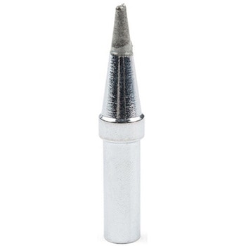 Soldering Tip - Weller - Screwdriver ETASPARKFUN
¥1,598税込¥1,758
1個
33日以内出荷
DescriptionThis is an ET Series replacement soldering tip for the Weller WE1010 soldering station. It is a "screwdriver" type of soldering tip, measuring 1/16"(1.6mm)wide. Replacing the tip is a breeze --- simply unscrew the currently attached tip, slip the replacement tip in, and screw it into place.This Weller tip has been pre-tinned with a lead-free alloy. Although this soldering tip is called a "screwdriver," this is in name only and functions in no way similar to the tool it is named after.
アズワン品番67-0428-29
 Shapeoko 4 XL - Hybrid Table, with RouterSPARKFUN
¥739,800税込¥813,780
1個
33日以内出荷
DescriptionPlease note, these machines are built to order have an estimated lead time of 4 business days before shippingThis is the Shapeoko 4 XL, nearly double the cutting area of the Shapeoko 4 Standard! The Shapeoko is a 3-axis CNC Machine kit that allows you to create your 2D and 3D designs out of non-ferrous metals, hardwoods, and plastics. The Shapeoko 4 XL is designed to be affordable enough for any shop and powerful enough to do real work. Don't let the size intimidate you! This is an entry-level CNC machine designed for hobbyists, artists, and fabricators!Each Shapeoko 4 XL has a cutting area of 838.2mm(X)x 444.5 mm(Y)x 101.6mm(Z)(33"×17.5"×4")and an overall footprint of 1270mm(X)x 609.6mm(Y)x 482.6mm(Z)(50"×24"×19"). The power cable included in this kit is designed for the United States National Plug Standard. Don't forget you can put whatever you want on the adapter ring(as long as it fits), whether that's a laser, 3D print extrusion head, or a marker. Get creative!Upgrades from the Shapeoko 3 include:New, more rigid v-wheel design15mm beltsInductive homing switchesNew electronicsIntegrated t-slot Hybrid Table(OPTIONAL)Fully-supported Y extrusionsLeadscrew-driven Z-axisNew, more rigid 65mm router mountSweepy 65mm V2 dust bootNote:This item is non-returnable. If this item arrives damaged or is not functioning properly, please do not hesitate to contact us to see if further actions may be taken.Not Compatible with the Shapeoko 4:Expansion PacksT-Track Clamp KitsZ-PlusProximity Switch KitMaintenance KitShapeoko 3 Bit SetterHDZ 4.0FeaturesFootprint:1270mm×609.6mm×482.6mm(50"×24"×19")Cutting Area:838.2mm×444.5mm×101.6mm(33"×17.5"×4")Weight 137lbs.Operating System:Mac(OSX 10.14 or higher)or PC(Windows 8.1 or 10, Intel or AMD)
アズワン品番67-0428-90
 RF Link Receiver - 4800bps 315MHzSPARKFUN
¥1,798税込¥1,978
1個
33日以内出荷
DescriptionThese wireless receivers work with our 315MHz transmitters. They can easily fit into a breadboard and work well with microcontrollers to create a very simple wireless data link. Since these are only receivers, they will only work communicating data one-way, you would need two pairs(of different frequencies)to act as a transmitter/receiver pair.Note:These modules are indiscriminate and will receive a fair amount of noise. Both the transmitter and receiver work at common frequencies and don't have IDs. Therefore, a method of filtering this noise and pairing transmitter and receiver will be necessary. The example code below shows such an example for basic operation. Please refer to the example code and links below for ways to accomplish a robust wireless data link.Note:These receivers are almost identical to the RF link 434MHz receiver. SparkFun does everything in our power to make sure you receive the product you requested. However, if you are concerned you may have received the incorrect product you can verify which version receiver this is by running a simple test circuit.Features315 MHz500ft range(given perfect conditions)4800bps data rate5V supply voltage
アズワン品番67-0430-44
 Raspberry Pi 4 Compute Module Antenna KitSPARKFUN
¥3,500税込¥3,850
1個
予約販売
DescriptionThis is the Antenna Kit for the Raspberry Pi 4 Compute Module wireless variants. The "duck" style antenna adds range to the wireless radio on the wireless enabled Compute Modules. Something quite desirable if you're working in industrial environments or other places a Compute Module would be used and the potential for signal interference is present. The antenna connects to the board via the press-fit U.FL connector on board the compute module(see photos for more details).This kit contains an antenna, bulkhead fixture, and SMA to U.FL Cable.FeaturesFrequency range:2400-2500/5100-5800 MHzBandwidth:100-700MHzVSWR:≦ 2.0Gain:2 dBiImpedance:50 ohmPolarisation:VerticalRadiation:OmnidirectionalMaximum power:10WAntenna dimensions:108 mm×10 mm
アズワン品番67-0429-69
 Poke Home Connector - 2-PinSPARKFUN
¥129税込¥142
1個
33日以内出荷
DescriptionPoke Home Connectors have been featured on a number of our boards over the last few years by providing a simple screw-terminal-type connector for easy wire connection purposes. Similar to screw terminals, Poke Home Connectors grasp a wire entered into the receiving area of the pin-out by pressing down on the small plastic strip at the end of the housing. Doing so raises the internal clamp and, upon release of the button secures the wire in place without any soldering required.Poke Home Connectors work better in environments with a lot of vibrations(i.e. automotive applications)or when a wire is expanding or contracting due to temperature cycling. Additionally, the tension in the connector is automatically adjusted to the wire gauge(assuming it is within the accepted wire thickness)as opposed to variances in tension when a user tightens the screw terminal.
アズワン品番67-0425-83
 PicoBuck LED DriverSPARKFUN
¥4,798税込¥5,278
1個
33日以内出荷
DescriptionThe PicoBuck LED Driver is an economical and easy to use driver that will allow you to control and blend three different LEDs on three different channels. By default, each channel is driven at 330mA; that current can be reduced by either presenting an analog voltage or a PWM signal to the board. Version 12 of the board adds a solderable jumper that can be closed to increase the maximum current to 660mA. The new voltage regulator also increased the voltage rating on the various components on the board, allowing it to be used up to the full 36V rating of the AL8805 part.Three signal inputs are provided for dimming control. You can use the PWM signal from an Arduino or your favorite microcontroller to dim each channel individually, or you can tie them all to the same PWM for simultaneous dimming. Dimming can be done by an analog voltage(20%-100% of max current by varying voltage from .5V-2.5V)or by PWM(so long as PWM minimum voltage is less than .4V and maximum voltage is more than 2.4V)for a full 0-100% range. A small jumper is provided for each channel to allow you to increase the drive strength from 330mA to 660mA. Two mounting holes for 4-40 or M3 screws are provided on either side of the board. They are perforated so they can be easily snapped off with a pair of pliers, if a smaller footprint is desired.Note:If you're going to use screw terminals, this board uses two different sizes. Check the related products for both sizes you'll need.Note:The PicoBuck LED Driver was made in collaboration with Ethan Zonca. A portion of each sale is given back to him.
アズワン品番67-0420-83
 PCB Engraver - #502 2 PackSPARKFUN
¥13,980税込¥15,378
1個
33日以内出荷
DescriptionThis is a two pack of #502 PCB engravers from Carbide 3D for your Shapeoko or Nomad CNC machine to supply you with even more fabrication and milling options. Each PCB engraver possesses a 0.005" ball tip with a 0.0025" radius, a 40 degree tip angle, and is made of solid carbide to ensure long lasting use.If you are wondering how best to utilize this kit, make sure to check out the free to use web app, Carbide Copper. Carbide Copper is CAM software to let you mill PCBs with your CNC machine and is the fastest way to make same-day circuit boards in your own office or shop.Note:It is recommended to use this PCB engraver with FR1 copper clad rather than FR4 to ensure you give your tool bit the longest life possible.Features0.005" Ball tip(0.0025" radius)40 Degree Tip Angle0.125" Shank2 FlutesSolid Carbide
アズワン品番67-0428-37
 PCB Engraver - #501 2 PackSPARKFUN
¥13,980税込¥15,378
1個
33日以内出荷
DescriptionThis is a two pack of #501 PCB engravers from Carbide 3D for your Shapeoko or Nomad CNC machine to supply you with even more fabrication and milling options. Each PCB engraver possesses a 0.1" ball tip with a 0.005" radius, a 60 degree tip angle, and is made of solid carbide to ensure long lasting use.If you are wondering how best to utilize this kit, make sure to check out the free to use web app, Carbide Copper. Carbide Copper is CAM software to let you mill PCBs with your CNC machine and is the fastest way to make same-day circuit boards in your own office or shop.Note:It is recommended to use this PCB engraver with FR1 copper clad rather than FR4 to ensure you give your tool bit the longest life possible.Features0.00" Ball tip(0.005" radius)60 Degree Tip Angle0.125" Shank2 FlutesSolid Carbide
アズワン品番67-0428-38
 microSD Card with Adapter-32GB Class10SPARKFUN
¥8,198税込¥9,018
1個
33日以内出荷
DescriptionThis is a class 10 32GB microSD memory card, perfect for housing operating systems for single board computers and a multitude of other information. Since this is a class 10 microSD it is capable of transferring data at speeds up to 80MB/s allowing it to have a noticeable increase in performance while running an on-board OS.Each microSD card comes with its own SD adapter for better ease of access.FeaturesClass 10(up to 80MB/s read-write)32GB Storage
アズワン品番67-0359-07
 Load Cell - 200kg, S-Type TAS501SPARKFUN
¥27,980税込¥30,778
1個
予約販売
DescriptionThis S-Type load cell(sometimes called a strain gauge)can translate up to 200kg of pressure(force)into an electrical signal. Each load cell is able to measure the electrical resistance that changes in response and proportion to the strain(e.g., pressure or force)applied to the form. With this gauge you will be able to tell just how heavy an object is, if an object's weight changes over time, or if you simply need to sense the presence of an object by measuring strain or load applied to a surface.Each straight bar load cell is made from an alloy steel and is capable of reading a capacity up to 200kg. These load cells have four strain gauges that are hooked up in a Wheatstone bridge formation. The color code on the wiring is as follows:red = E+, green = O+, black = E-, and white = O-. Additionally, these load cells offer an IP66 protection rating and feature two M4 and two M5 sized through-holes for mounting purposes.Get Started with the Load Cell GuideFeatures51mm×19mm×76mm, 3m Wire
アズワン品番67-0426-66
 Load Cell - 10kg, Straight Bar TAL220SPARKFUN
¥3,998税込¥4,398
1個
予約販売
DescriptionThis straight bar load cell(sometimes called a strain gauge)can translate up to 10kg of pressure(force)into an electrical signal. Each load cell is able to measure the electrical resistance that changes in response to, and proportional of, the strain(e.g. pressure or force)applied to the bar. With this gauge you will be able to tell just how heavy an object is, if an object's weight changes over time, or if you simply need to sense the presence of an object by measuring strain or load applied to a surface.Each straight bar load cell is made from an aluminum-alloy and is capable of reading a capacity of 10kg. These load cells have four strain gauges that are hooked up in a wheatstone bridge formation. The color code on the wiring is as follows:red = E+, green = O+, black = E-, and white = O-. Additionally, these load cells offer an IP66 protection rating and feature two M4 and two M5 sized through-holes for mounting purposes.Get Started with the Load Cell GuideFeatures80mm×12.7mm×12.7mm, 250mm Wire
アズワン品番67-0426-52
 LilyPad LED White 5pcsSPARKFUN
¥969税込¥1,066
1個
33日以内出荷
DescriptionThis is a simple pack of five White LilyPad LEDs that are still attached to one another, letting you snap the LEDs apart at your leisure to sew into clothing or whatever else you can dream up.LilyPad is a wearable e-textile technology developed by Dr. Leah Buechley and cooperatively designed by Leah and SparkFun. Each LilyPad piece was creatively designed with large sew tabs to allow them to be sewn into fabric. Various input, output, power and sensor boards are available. They're even washable(with special care)!Note:A portion of this sale is given back to Dr. Buechley for continued development and education in e-textiles.Features5.5mm x 12.5mmThin 0.8mm PCB
アズワン品番67-0422-26
 LIDAR-Lite v3HPSPARKFUN
¥37,980税込¥41,778
1個
33日以内出荷
DescriptionLIDAR has never looked so good! This is the LIDAR-Lite v3HP, a compact, high-performance optical distance measurement sensor from Garmin(TM). The LIDAR-Lite v3HP istheideal optical ranging solution for drone, robot, or unmanned vehicle applications. Each sensor is housed in a durable, IPX7-rated housing and includes all the core features and user configurability of the popular LIDAR-Lite v3.The v3HP is very similar in function to that of the v3 but it can now sample faster at rates greater than 1kHz(where as the v3 is only capable of up to 500Hz). Another improvement is that this v3HP model is more power efficient with current consumption rates 40mA less than the v3(that's 65mA as opposed to 105mA while idle, and 85mA instead of 130mA while acquiring).Each LIDAR-Lite v3HP has a range of 1m to 40m and features an edge-emitting, 905nm(1.3 watts), single-stripe laser transmitter, 8m Radian beam divergence, and an optical aperture of 12.5mm. This version of the LIDAR-Lite still operates at 5VDC(6V max)with a peak power of 1.3W and still possesses an accuracy of +/- 2.5cm at >2m. On top of everything else, the LIDAR-Lite is user-configurable, allowing adjustment between accuracy, operating range and measurement time and can be interfaced via I2C or PWM with the attached 200mm cable.Note:CLASS 1 LASER PRODUCT CLASSIFIED EN/IEC 60825-1 2014. This product is in conformity with performance standards for laser products under 21 CFR 1040, except with respect to those characteristics authorized by Variance Number FDA-2016-V-2943 effective September 27, 2016.Get Started with the LIDAR-Lite v3HP GuideFeaturesResolution:1 cmTypical accuracy:+/- 2.5cm at distances greater than 2 meters(Refer to operating manual for complete operating specifications)Range:1m to 40mUpdate rate:Greater than 1kHzInterface:I2C or PWMPower(operating voltage):4.75-5VDC; 6V MaxCurrent consumption:65ma idle; 85ma during acquisitionOperating temperature:-20℃ to 60℃Laser wave length/Peak power:905nm/1.3WBeam divergence:8m RadianOptical aperture:12.5mmWater rating:IPX7Unit dimensions:24.5mm×53.5mm×33.5mm(1.0in×2.1in×1.3in)Weight:34g(1.2oz)
アズワン品番67-0426-76
 Iridium/GPS/GLONASS Passive AntennaSPARKFUN
¥23,980税込¥26,378
1個
33日以内出荷
DescriptionThe M1600HCT-P-SMA is unique antenna combining the ability to communicate with the Iridium satellite network while simultaneously receiving L1 GNSS signals(GPS and GLONASS). This makes the M1600HCT the perfect antenna for tracking devices that transmit their position over Iridium. In addition, weighing only 11 grams, the antenna can achieve IP67 when seated against an SMA bulkhead connection(there is a small o-ring built into the base).This product is designed for applications requiring high quality reception of the Iridium network and is ideal when:the orientation of the unit containing the antenna is random, the unit is used in harsh environments, and/or the antenna is mounted externally and in close proximity to other antennas.FeaturesFrequencyGPS(1575 MHz)GLONASS(1602 MHz)Iridium(1616 - 1626 MHz)Polarization:RHCPPeak Gain:GPS:-3 dBicGLONASS:0 dBicIridum:2.8 dBicImpedance:50 OhmRF Connector:SMADimensions:48mm×18.5mmWeight:11g
アズワン品番67-0423-85
 Flexible Qwiic Cable - 200mmSPARKFUN
¥649税込¥714
1個
33日以内出荷
DescriptionThis is a 200mm long 4-conductor cable with 1mm JST termination. It's designed to connect Qwiic enabled components together but can be used for other applications as well. The cable insulation is made from a highly malleable material making it more flexible than our original Qwiic cable particularly in tight spaces or enclosures.Each Qwiic Cable's wires have been color coded to red, black, blue and yellow.The SparkFun Qwiic connect system is an ecosystem of I2C sensors, actuators, shields and cables that make prototyping faster and less prone to error. All Qwiic-enabled boards use a common 1mm pitch, 4-pin JST connector. This reduces the amount of required PCB space, and polarized connections mean you can't hook it up wrong.FeaturesDimensions:200mm(7.87")Length
アズワン品番67-0426-04
 Flat Cutter - 0.125" Diameter, #102 3 PackSPARKFUN
¥11,980税込¥13,178
1個
33日以内出荷
DescriptionThis is a three pack of flat mills from Carbide 3D that are perfect for roughing or machining flat or prismatic parts. Each mill in this pack features a cutting and shank diameter of 0.125 inches and a cutting length of 0.5 inches. These cutters provide you with a specialized tool for 3D machining and fabrication.Each cutter is made of solid carbide to ensure long lasting use.FeaturesCutting Diameter:0.125inCutting Length:0.5inShank Diameter:0.125in
アズワン品番67-0428-42
 Flat Cutter - 0.0312" Diameter, #122 3 PackSPARKFUN
¥14,980税込¥16,478
1個
33日以内出荷
DescriptionThis is a three pack of flat mills from Carbide 3D that are perfect for fabricating flat or prismatic surfaces. Each mill in this pack features a cutting diameter of 0.0312 inches, a shank diameter of 0.125 inches, and a cutting length of 0.0625 inches. These cutters really are great for precision 3D machining and fabrication.Each cutter is made of solid carbide to ensure long lasting use.FeaturesCutting Diameter:0.0312"Cutting Length:0.0625"Shank Diameter:0.125"
アズワン品番67-0428-46
 Extended GPIO Female Header - 2x20 Pin 16mm/7.30mmSPARKFUN
¥939税込¥1,033
1個
予約販売
DescriptionThis 2x20 pin female header is meant to allow you to extend the reach of any board with the standard 2x20 GPIO pin footprint like the Raspberry Pi, Google Coral, and NVIDIA Jetson. You can also solder it to Pi HATs that do not have headers on the board. This is assuming that the board is only populated on the top of the board or the height of the components do not get in the way if it is a two layer board.The pin header is 16mm in height and the pin length is 7.30mm. This header also has standard 0.1" spacing.Note:Please note that this product is just the header. The Raspberry Pi, enclosure, Pi Wedge, and breadboard are sold separately.
アズワン品番67-0425-86
 Extended GPIO Female Header - 2x20 Pin 13.5mm/9.80mmSPARKFUN
¥899税込¥989
1個
予約販売
DescriptionThis 2x20 pin female header is meant to allow you to extend the reach of any board with the standard 2x20 GPIO pin footprint like the Raspberry Pi, Google Coral, and NVIDIA Jetson. You can also solder it to Pi HATs that do not have headers on the board. This is assuming that the board is only populated on the top of the board or the height of the components do not get in the way if it is a two layer board.The pin header is 13.5mm in height and the pin length is 9.80mm. This header also has standard 0.1" spacing.Note:Please note that this product is just the header. The Raspberry Pi, enclosure, Servo pHAT, and Qwiic SHIM are sold separately.
アズワン品番67-0425-87
 Cable Carrier - 10x15mm 0.5m LengthSPARKFUN
¥4,398税込¥4,838
1個
予約販売
DescriptionNo, this isn't a tank tread, this is a 0.5m long Cable Carrier with 10x15mm bits composing its main body and two screw fasteners at each end for efficient mounting. Sometimes called a "drag chain," each carrier can be used in projects with a large number of moving parts to protect internally installed cables, pipes, or tubes so they can be bent and moved while remaining protected. Cable carriers can most commonly been found in 3D printers and CNC machines but they can be used in any situation where you need cables or tubes to bend without risk of them being damaged or wearing out prematurely.This specific cable carrier offers inner dimensions of 10mm(height)by 15mm(wide), an outer width of 22mm, and a bend radius of 20mm. Additionally, these carriers are thin enough to fit into an Actobotics channel, making custom slide machines or other projects even easier to manage. Much like a chain, individual links can be added or removed to make custom lengths.FeaturesInner Bit Height:10mmInner Bit Width:15mmOuter Bit Height:14Outer Bit Width:22mmMinimum Bend Radius:20mmReinforced Nylon Structure
アズワン品番67-0426-29
 SparkFun Qwiic Alphanumeric Display - COMシリーズSPARKFUN
¥2,298税込¥2,528
1個
33日以内出荷
DescriptionThe SparkFun Alphanumeric Display Arduino library makes printing strings to the display as easy as calling the print()function. With this library, you'll be able to send I2C commands to the VK16K33 LED driver chip to light up segments(including the decimal point or colon)and even scroll your string across the display. You can download the library through the Arduino library manager by searching 'SparkFun Alphanumeric Display' or you can get the GitHub repo as a .zip file and install the library from there.The SparkFun Qwiic Connect System is an ecosystem of I2C sensors, actuators, shields and cables that make prototyping faster and less prone to error. All Qwiic-enabled boards use a common 1mm pitch, 4-pin JST connector. This reduces the amount of required PCB space, and polarized connections mean you can't hook it up wrong.Get Started with the Qwiic Alphanumeric Display Hookup GuideFeaturesOperating Voltage:3.3VIntegrated RC oscillatorMaximum display segment numbers:128 patterns13×3 matrix key scan circuit16-step dimming circuitI2C Addresses:0x70(0x71, 0x72, 0x73)2x Qwiic connectors2x Wall Mounting Points
アズワン品番67-0421-62
 SparkFun LuMini LED Ring - Inch COMシリーズSPARKFUN
¥2,798税込¥3,078
1個
33日以内出荷
DescriptionNote:In larger installations you may need to add a decoupling capacitor between power and ground to prevent voltage dips when turning on a whole bunch of LED's simultaneously. We recommend using a 4.7μF capacitor which we sell in strips of 10.Get Started With the SparkFun LuMini LED Ring GuideFeaturesOptional Capacitor SpaceDaisy-Chainable
アズワン品番67-0421-23
 Breadboard to Cable - Pitch CABシリーズSPARKFUN
¥799税込¥879
1個
予約販売
DescriptionFeatures28 AWG
アズワン品番67-0420-73
 XBee 3 Pro Module - U.FL AntennaSPARKFUN
¥11,980税込¥13,178
1個
33日以内出荷
DescriptionAfter years of popularity with the XBee Series 1 and XBee Series 2 Pro Modules, we now have the XBee Series 3 Pro which brings the best of both worlds. XBee 3 not only handles 802.15.4, and ZigBee, but also BLE protocols and you can now talk to the modules over UART or SPI as well. With a 300ft indoor range, or 2mile outdoor/line-of-sight range, you can set up a mesh network to talk to or communicate with various devices around your house, work, or other area.This module has the familiar XBee package while sporting a U.FL connector to add an antenna. You also get a built in microcontroller so you can also configure and program the modules using MicroPython as well as Digi's XCTU software. With a HCS08 CPU running at up to 50.33MHz, 15x digital I/O pins, and 4x 10-bit ADC pins these modules can even hold their own as a microcontroller.Note:While these are backwards compatible in many ways with the XBee 1s and 2s, they are not completely compatible. Please see documentation for differences if you plan on adding these to an existing project.FeaturesRF 250Kbps, Serial 1Mbps300ft(indoor)to 2 mile(outdoor)rangeTransmit power +19dBM @ 135mAReceiver Sensitivity -103dBm @ 15mA4x 10-bit ADC inputs15x Digital I/O pinsHCS08 CPU at up to 50.33MHz128/256 bit AES Encryption2.1V to 3.6V operating voltage1.7 μA power-down currentBuilt in RS-485 supportAT command or API frame supportFCC Certified
アズワン品番67-0429-52
 U.FL to U.FL Mini Coax Cable - 200mmSPARKFUN
¥989税込¥1,088
1個
予約販売
DescriptionThis cute little coax is a champ in our RF kit! It has a right angle female U.FL(aka I-PEX)connector on both ends. Now instead of jerry-rigging a few U.FL to SMA cables together we can go straight from one U.FL device to another. As an added bonus this coax is the nice stuff - approximately 1mm in diameter and extra flexible. The 50-ohm impedance of this cable makes it well suited for almost all SparkFun RF products including GPS, LoRa, and RFID.Features200 mm length1.25 mm diameterU.FL connectors on both ends(cable side, to mate with SMD board connector)
アズワン品番67-0429-49
 TRRS Audio Plug - 3.5mm MetalSPARKFUN
¥519税込¥571
1個
予約販売
DescriptionTRRS connectors are the audio-style connectors that you see on some phones, MP3 players and development boards. TRRS stands for "Tip, Ring, Ring, Sleeve," which reflects the fact that, unlike a standard stereo connector, this actually has three conductors and a ground. Some devices use the extra conductor for a microphone(like hands-free headsets)or to carry a video signal(like in some MP3/MP4 players). If you're hacking on something that has a 4-conductor audio jack, being able to plug straight in will keep your build clean and simple.Note:This plug allows you to add a custom length of wire to your connector or repair a broken shroud on an existing cable you just cannot live without. Unfortunately, the supplier has not provided a datasheet or dimensional drawing please see the similar documents provided by other SparkFun products on the "documents" tab.
アズワン品番67-0421-42


対応外付HDD(ハードウェア暗号化/電源内蔵モデル) I ・O DATA(アイ・オー・データ)")