


絞り込み
ブランド
- SPARKFUN
- Seeed Studio(14)
- EVANS(12)
- Electro Harmonix(8)
- ケニス(7)
- Elecfreaks(7)
- アーテック[学校教材・教育玩具](6)
- Kitronik(3)
- CRECOTE(2)
- DIGILENT(1)
- ナリカ(1)
- アルテージュ(1)
- スイッチエデュケーション(1)
商品レビュー
- 以上(0)
- 以上(0)
- 以上(0)
- 以上(0)
価格
- 1,500円以下(19)
- 1,500-10,000円(63)
- 10,000-50,000円(33)
- 50,000-100,000円(1)
- 100,000円以上(4)
価格で絞り込む
出荷目安
- 当日
- 翌日以内
- 翌々日以内
- 3日以内
- 4日以内
当日・翌日以内・翌々日以内・3日以内・4日以内
その他
- 取扱い終了商品を除く
- 個人購入不可商品を除く

 MPLAB PICkit 4 In-Circuit DebuggerSPARKFUN
¥45,980税込¥50,578
1個
当日出荷
DescriptionThis is the PICkit 4, the official programmer from Microchip. The PICkit 4 allows debugging and programming of PIC(R), dsPIC(R), AVR, SAM and CEC flash microcontrollers and MPUs using the powerful graphical user interface of the MPLAB X Integrated Development Environment(IDE). The MPLAB PICkit 4 is connected to a PC using a high-speed 2.0 USB interface and can be connected to the target via an 8-pin Single In-Line(SIL)connector. The connector uses two device I/O pins and the reset line to implement in-circuit debugging and In-Circuit Serial Programming(TM)(ICSP(TM)). An additional micro SD card slot and the ability to be self-powered from the target means you can take your code with you and program on the go. Comes with a USB to micro-B USB cable.FeaturesPowered by a high-speed USB 2.0, no external power requiredReal-time executionMPLAB X IDE compatible(free copy included)Built-in over-voltage/short circuit monitorFirmware upgradeable from PC/web downloadFully enclosedTarget voltage of 1.20V to 5.5VCan supply up to 50mA of power to the targetMinimal current consumption at <100μA from targetDiagnostic LEDs(power, busy, error)Read/write program and data memory of microcontrollerErase of program memory space with verificationFreeze-peripherals at breakpoint8-pin single in-line header supports advanced interfaces such as 4-wire JTAG and Serial Wire Debug with streaming Data GatewayBackward compatible for demo boards, headers and target systems using 2-wire JTAG and ICSP
アズワン品番67-0425-08
 Elektor STM32 Nucleo Starter KitSPARKFUN
¥16,980税込¥18,678
1個
33日以内出荷
DescriptionThe Elektor STM32 Nucleo Starter Kit is the perfect entry point into the world of the widely popular STM32 microcontroller line. This bundle covers many projects using most features of the STM32 Nucleo development boards with the full softw
アズワン品番67-0424-72
 ArduinoMega 2560 R3SPARKFUN
¥18,980税込¥20,878
1個
33日以内出荷
DescriptionArduino is an open-source physical computing platform based on a simple i/o board and a development environment that implements the Processing/Wiring language. Arduino can be used to develop stand-alone interactive objects or can be connected to software on your computer(e.g. Flash, Processing, MaxMSP). The open-source IDE can be downloaded for free(currently for Mac OS X, Windows, and Linux).The Arduino Mega is a microcontroller board based on the ATmega2560. It has 54 digital input/output pins(of which 14 can be used as PWM outputs), 16 analog inputs, 4 UARTs(hardware serial ports), a 16 MHz crystal oscillator, a USB connection, a power jack, an ICSP header, and a reset button. It contains everything needed to support the microcontroller; simply connect it to a computer with a USB cable or power it with a AC-to-DC adapter or battery to get started.Never fear for accidental electrical discharge, either since since the Mega also includes a plastic base plate to protect it!The Mega 2560 R3 also adds SDA and SCL pins next to the AREF.In addition, there are two new pins placed near the RESET pin. One is the IOREF that allow the shields to adapt to the voltage provided from the board.The other is a not connected and is reserved for future purposes.The Mega 2560 R3 works with all existing shields but can adapt to new shields which use these additional pins.Not sure which Arduino or Arduino-compatible board is right for you? Check out our Arduino Buying Guide!FeaturesATmega2560 microcontrollerInput voltage - 7-12V54 Digital I/O Pins(14 PWM outputs)16 Analog Inputs256k Flash Memory16Mhz Clock Speed
アズワン品番67-0349-13
 SparkFun Cryptographic Co-Processor Breakout - ATECC608A QwiicSPARKFUN
¥1,498税込¥1,648
1個
33日以内出荷
DescriptionProduct Restrictions:To access certain features of the ATECC608A, users will need to contact Microchip and sign an NDA contract to obtain the complete datasheet. Due to the required NDA - technical support, an Arduino library, and hookup guide are not provided for users on this product.The SparkFun ATECC608A Cryptographic Co-processor Breakout allows you to add strong security to your IoT node, edge device, or embedded system. This includesasymmetricauthentication,symmetricAES-128 encryption/decryption, and much more. As stated above, the ATECC608A has limited Arduino support and the complete datasheet is under NDA with Microchip.This breakout board includes two Qwiic ports for plug and play functionality. Utilizing our handy Qwiic system, no soldering is required to connect it to the rest of your system. However, we still have broken out 0.1"-spaced pins in case you prefer to use a breadboard. The ATECC608A chip is capable of many cryptographic processes, including, but not limited to:Creating and securely storing unique asymmetric key pairs based on Elliptic Curve Cryptography(FIPS186-3).AES-128:Encrypt/Decrypt, Galois Field Multiply for GCMCreating and verifying 64-byte digital signatures(from 32-bytes of message data).Creating a shared secret key on a public channel via Elliptic Curve Diffie-Hellman Algorithm.SHA-256 HMAC Hash including off-chip context save/restoreInternal high quality FIPS random number generator.Embedded in the chip is a 10Kb EEPROM array that can be used for storing keys, certificates, data, consumption logging, and security configurations. Access to the sections of memory can then be restricted and the configuration locked to prevent changes. Each ATECC608A Breakout ships with a guaranteed unique 72-bit serial number and includes several security features to prevent physical attacks on the device itself, or logical attacks on the data transmitted between the device.A summary datasheet for the ATECC608A is available here. The full datasheet is under NDA with Microchip. You will need to contact them for access to the entire datasheet. Meanwhile, the ArduinoATECCX08 Library currently only supports the ATECC608A with SAMD21 Arduino boards.We do have much more support for the ATECC508A version of this chip. Please check out our ATECC508A Hookup Guide and Arduino Library(which includes six examples). This will get you familiar with the basics of elliptic curve cryptography and signing/verifying data with the ATECC508A version of the chip.Note:The I2C address of the ATECC608A is 0x60 and is software-configurable to any address. A multiplexer/Mux is required to communicate to multiple ATECC608A sensors at the default address when on a single bus. If you need to use more than one ATECC608A sensor at the default address, consider using the Qwiic Mux Breakout.Note:The ATECC608A can be only configured once before it isPERMANENTLYlocked. It is advisable that users purchase multiple boards in order to use other configurations and explore the advanced functions of the ATECC608A.Additionally, this boardIScapable of encrypting and decrypting data. However, to access these additional features, you will need to contact Microchip and sign an NDA contract to obtain the complete datasheet.It is recommended that an SparkFun RedBoard Turbo - SAMD21 Development Board is used with this product due to the buffer size required on the I2C bus.The SparkFun Qwiic Connect System is an ecosystem of I2C sensors, actuators, shields and cables that make prototyping faster and less prone to error. All Qwiic-enabled boards use a common 1mm pitch, 4-pin JST connector. This reduces the amount of required PCB space, and polarized connections mean you can't hook it up wrong.FeaturesOperating Voltage:2.0V-5.5V(Default on Qwiic System:3.3V)Active Current Draw(for ATECC608A):16 mASleep Current(for ATECC608A):<150 nAGuaranteed Unique 72-bit Serial Number10 Kb EEPROM Memory for Keys, Certificates, and DataStorage for up to 16 Keys256-bit Key LengthInternal High-Quality FIPS Random Number Generator(RNG)Configurable I2C Address(7-bit):0x60(Default)
アズワン品番67-0423-59
 SparkFun FTDI Starter Kit - 3.3VSPARKFUN
¥5,998税込¥6,598
1個
33日以内出荷
DescriptionThe SparkFun 3.3V FTDI Starter Kit gives you just what you need to get started with FTDI FT232RL USB to serial IC. The pinout of the included board matches the FTDI cable standard to work with official Arduino and cloned 3.3V Arduino boards. It can also be used for general serial applications. The major difference with this board is that it brings out the DTR pin as opposed to the RTS pin of the FTDI cable. The DTR pin allows an Arduino target to auto-reset when a new Sketch is downloaded. This is a really nice feature to have and allows a sketch to be downloaded without having to hit the reset button. This board will auto reset any Arduino board that has the reset pin brought out to a 6-pin connector.The SparkFun FTDI Basic Breakout was designed to decrease the cost of Arduino development and increase ease of use(the auto-reset feature rocks!). Our Arduino Pro and LilyPad boards use this type of connector.The included cable is a USB 2.0 type B to Mini-B 5-pin black cable.
アズワン品番67-0424-75
 GPS/GNSS Embedded Antenna - 1m SMASPARKFUN
¥29,980税込¥32,978
1個
欠品中
DescriptionThis tri-band GNSS antenna is ideal for GPS L1, GLONASS L1, and Beidou B2 reception. At 45x45mm it is alargeceramic antenna with an incredible 38dB LNA gain.This antenna works well with the GPS-RTK providing reception of Beidou satellites where other more basic GPS antennas cannot. We've chosen to have the antenna manufactured without an enclosure to decrease the weight(45g including cable)making this antenna more ideal for rover and quad-copter applications. Additionally, the cable length has been reduced to 1m to reduce weight and to make a more clean installation.We recommend this antenna for RTK use when combined with the ground plate. This antenna is ideal for advanced raw, RTK, and post-processed measurements of GPS, GLONASS, and Beidou constellations. If all you need is GPS and GLONASS(basic GNSS)consider our lower cost magnetic mount GNSS antenna.Antenna is terminated with a standard SMA connector. Check out the related items below for any conversion cables you may need.FeaturesDimensions:45x45x9mmWeight:45g including 1m cableFrequency Range:1558 - 1615MHzLNA Voltage:3.3 to 15VDCPrimary Antenna Gain:4dBLNA Gain:38dBLNA Current:<= 35mATermination Connector:SMAImpedance:50ΩRight hand polarizationCable Length:1 meter
アズワン品番67-0423-73
 SparkFun Beefcake Relay Control Kit Ver. 2.0SPARKFUN
¥3,198税込¥3,518
1個
33日以内出荷
DescriptionYour 5V system can wield great power with this big, beefy relay board. How does 10A on the NC contacts and 20A on the NO contacts at 220VAC sound? The SparkFun Beefcake Relay Control Kit contains all the parts you need to get your high-power load under control. Only minimal assembly is required!The heart of the board is sealed, SPDT 20A/10A Relay. The relay is controlled by 5V logic through transistor, and an LED tells you when the relay is closed. This is kit, so it comes as through-hole parts with assembly required, which makes for some nice soldering practice. Screw terminal connectors on either side of the board make it easy to incorporate into your project.There are some pretty beefy traces connecting the relay to the load pins, but the 3-pin terminals are only rated for 15A max! If you plan on connecting larger load, you'll need to solder directly to the board. As always with high current and voltage, play it safe and use your judgment when deciding how much of load you want to put on board -- in open airflow the PCB can handle the full 20A for few minutes at time, but in an enclosed area heat can build up.Note:Please keep in mind that this board is really meant for someone with experience and good knowledge of electricity. If you're uncomfortable soldering or dealing with high voltage, please check out the IoT Power Relay. The IoT Power Relay is fully enclosed, making it lot safer.Get Started With the Beefcake Hookup Assembly GuideFeaturesVoltage Rating:220VAC/28VDCVCC requirements:4-6V, 150mA capableSPDT pins exposed(Form C)14 AWG screw terminals for relay connections.10 AWG solder lugs for relay connections.Flyback diode includedZener recovery diode included(decreases turn-off time)Heavy oz. copper on PCB
アズワン品番67-0424-03
 SparkFun Beefy 3 - FTDI Basic BreakoutSPARKFUN
¥5,798税込¥6,378
1個
33日以内出荷
DescriptionThis is SparkFun Beefy 3 FTDI Basic Breakout for the FTDI FT231X USB to serial IC. The pinout of this board matches the FTDI cable to work with official Arduino and cloned 3.3V Arduino boards. It can also be used for general serial applications. Built upon the same foundation as our 3.3V SparkFun FTDI Basic Breakout, the Beefy 3 is equipped with an AP2112K voltage regulator making this FTDI basic breakout board capable of handling a current load of up to 600 mA! With the addition of a more "Beefy" voltage regulator your will now be able to power a 3.3V project directly from the FTDI. The pinout of this board matches the FTDI cable to work with official Arduino and cloned 3.3V Arduino boards.This board brings out the DTR pin as opposed to the RTS pin of the FTDI cable. The DTR pin allows an Arduino target to auto-reset when a new Sketch is downloaded. This is a really nice feature to have and allows a sketch to be downloaded without having to hit the reset button. This board will auto reset any Arduino board that has the reset pin brought out to a 6-pin connector. The pins labeled BLK and GRN correspond to the colored wires on the FTDI cable. The black wire on the FTDI cable is GND, green is DTR. Use these BLK and GRN pins to align the FTDI basic board with your Arduino target.There are pros and cons to the FTDI Cable vs the FTDI Basic. This board has TX and RX LEDs that allow you to actually see serial traffic on the LEDs to verify if the board is working, however this board now requires a Micro-B USB cable. The FTDI Cable is well protected against the elements, but is large and cannot be embedded into a project as easily. The FTDI Basic uses DTR to cause a hardware reset where the FTDI cable uses the RTS signal.This board was designed to decrease the cost of Arduino development and increase ease of use(the auto-reset feature rocks!). Our Arduino Pro and LilyPad boards use this type of connector.
アズワン品番67-0430-06
 SparkFun GPS Breakout - ZOE-M8Q QwiicSPARKFUN
¥14,980税込¥16,478
1個
33日以内出荷
DescriptionThe SparkFun ZOE-M8Q GPS Breakout is a high accuracy, miniaturized, GPS board that is perfect for applications that don't possess a lot of space. The on-board ZOE-M8Q is a 72-channel GNSS receiver, meaning it can receive signals from the GPS, GLONASS, BeiDou, and Galileo constellations. This increases precision and decreases lock time and thanks to the onboard rechargable battery you'll have backup power enabling the GPS to get a hot lock within seconds! Additionally, this u-blox receiver supports I2C(u-blox calls this Display Data Channel)which made it perfect for the Qwiic compatibility so we don't have to use up our precious UART ports. Utilizing our handy Qwiic system, no soldering is required to connect it to the rest of your system. However, we still have broken out 0.1"-spaced pins in case you prefer to use a breadboard.U-blox based GPS products are configurable using the popular, but dense, windows program called u-center. Plenty of different functions can be configured on the ZOE-M8Q:baud rates, update rates, geofencing, spoofing detection, external interrupts, SBAS/D-GPS, etc. All of this can be done within the SparkFun Arduino Library. We've also made sure to configure the UART pin grouping on the breakout to an industry standard to insure that it easily connects to a Serial Basic.The SparkFun ZOE-M8Q GPS Breakout is also equipped with an on-board rechargeable battery that provides power to the RTC on the ZOE-M8Q. This reduces the time-to-first fix from a cold start(~30s)to a hot start(~1s). The battery will maintain RTC and GNSS orbit data without being connected to power for up to five hours. Since the ZOE-M8Q is a tiny GPS receiver and to minimize its footprint, we've added a U.FL connector to allow the use of both large standard ceramic antennas as well as very small chip scale antennas.Note:The I2C address of the ZOE-M8Q is 0x42 and is software configurable. A multiplexer/Mux is required to communicate to multiple ZOE-M8Q sensors on a single bus. If you need to use more than one ZOE-M8Q sensor consider using the Qwiic Mux Breakout.The SparkFun Qwiic Connect System is an ecosystem of I2C sensors, actuators, shields and cables that make prototyping faster and less prone to error. All Qwiic-enabled boards use a common 1mm pitch, 4-pin JST connector. This reduces the amount of required PCB space, and polarized connections mean you can't hook it up wrong.The ZOE-M8Q GPS Breakout can also be automatically detected, scanned, configured, and logged using the OpenLog Artemis datalogger system. No programming, soldering, or setup required!Get Started With the SparkFun ZOE-M8Q Hookup GuideFeatures72-Channel GNSS Receiver2.5m Horizontal Accuracy18Hz Max Update RateTime-To-First-Fix:Cold:26sHot:1sMax Altitude:50,000mMax G:≦4Max Velocity:500m/sVelocity Accuracy:0.05m/sHeading Accuracy:0.3 degreesTime Pulse Accuracy:30ns3.3V VCC and I/OCurrent Consumption:~29mA Tracking GPS+GLONASSSoftware ConfigurableGeofencingOdometerSpoofing DetectionExternal InterruptPin ControlLow Power ModeMany others!Supports NMEA, UBX, and RTCM protocols over UART or I2C interfaces
アズワン品番67-0423-76
 SparkFun GPS Breakout - NEO-M9N, SMA QwiicSPARKFUN
¥22,980税込¥25,278
1個
33日以内出荷
DescriptionThe SparkFun NEO-M9N GPS Breakout is a high quality GPS board with equally impressive configuration options including SMA. The NEO-M9N module is a 92-channel u-blox M9 engine GNSS receiver, meaning it can receive signals from the GPS, GLONASS, Galileo, and BeiDou constellations with ~1.5 meter accuracy. This breakout supports concurrent reception of four GNSS. This maximizes position accuracy in challenging conditions increasing, precision and decreases lock time; and thanks to the onboard rechargeable battery, you'll have backup power enabling the GPS to get a hot lock within seconds! Additionally, this u-blox receiver supports I2C(u-blox calls this Display Data Channel)which makes it perfect for the Qwiic compatibility so we don't have to use up our precious UART ports. Utilizing our handy Qwiic system, no soldering is required to connect it to the rest of your system. However, we still have broken out 0.1"-spaced pins in case you prefer to use a breadboard.The NEO-M9N module detects jamming and spoofing events and can report them to the host, so that the system can react to such events. A SAW(Surface Acoustic Wave)filter combined with an LNA(Low Noise Amplifier)in the RF path is integrated into the NEO-M9N module which allows normal operation even under strong RF interferences.U-blox based GPS products are configurable using the popular, but dense, windows program called u-center. Plenty of different functions can be configured on the NEO-M9N:baud rates, update rates, geofencing, spoofing detection, external interrupts, SBAS/D-GPS, etc. All of this can be done within the SparkFun Arduino Library!The SparkFun NEO-M9N GPS Breakout is also equipped with an on-board rechargeable battery that provides power to the RTC on the NEO-M9N. This reduces the time-to-first fix from a cold start(~24s)to a hot start(~2s). The battery will maintain RTC and GNSS orbit data without being connected to power for plenty of time.This product requires an antenna:Be sure to check out the related products/hookup accessories and pick a suitable SMA antenna for your project.The SparkFun Qwiic Connect System is an ecosystem of I2C sensors, actuators, shields and cables that make prototyping faster and less prone to error. All Qwiic-enabled boards use a common 1mm pitch, 4-pin JST connector. This reduces the amount of required PCB space, and polarized connections mean you can't hook it up wrong.The NEO-M9N GPS Breakout can also be automatically detected, scanned, configured, and logged using the OpenLog Artemis datalogger system. No programming, soldering, or setup required!Get Started With the SparkFun NEO-M9N GPS GuideFeaturesIntegrated SMA connector for use with antenna of your choice92-Channel GNSS Receiver1.5m Horizontal Accuracy25Hz Max Update Rate(four concurrent GNSS)Time-To-First-Fix:Cold:24sHot:2sMax Altitude:80,000mMax G:≦4Max Velocity:500m/sVelocity Accuracy:0.05m/sHeading Accuracy:0.3 degreesTime Pulse Accuracy:30ns3.3V VCC and I/OCurrent Consumption:~31mA Tracking GPS+GLONASSSoftware ConfigurableGeofencingOdometerSpoofing DetectionExternal InterruptPin ControlLow Power ModeMany others!Supports NMEA, UBX, and RTCM protocols over UART or I2C interfaces
アズワン品番67-0423-87
 SparkFun Cryptographic Co-Processor Breakout - ATECC508A QwiicSPARKFUN
¥2,698税込¥2,968
1個
欠品中
DescriptionThe SparkFun ATECC508A Cryptographic Co-Processor Breakout allows you to easily add strong authentication security to your IoT node, edge device, or embedded system. It includes two Qwiic ports for plug and play functionality. Utilizing ou
アズワン品番67-0422-83
 SparkFun Electret Microphone BreakoutSPARKFUN
¥2,898税込¥3,188
1個
欠品中
DescriptionThis small breakout board couples an Electret microphone(100Hz--10kHz)with a 60x mic preamplifier to amplify the sounds of voice, claps, door knocks or any sounds loud enough to be picked up by a microcontroller's analog-to-digital converter. Each breakout comes fully assembled and works from 2.7V up to 5.5V.The Electret Mic Breakout translates amplitude(not volume)by capturing sound waves between two conducting plates(one a vibrating diaphragm and the other fixed)in the microphone and converting them into electrical waves. These electrical signals are then amplified and picked up by your microcontroller's ADC.Get Started With the Electret Microphone Guide!
アズワン品番67-0419-83
 SparkFun Paper Circuits KitSPARKFUN
¥5,198税込¥5,718
1個
33日以内出荷
DescriptionWelcome to the world of paper circuits - creating electronic projects directly on paper using simple components! The SparkFun Paper Circuits Kit teaches the basics and fundamentals of creating an electric circuit without the need to solde
アズワン品番67-0424-37
 SparkFun Distance Sensor Breakout - 4 Meter, VL53L1X QwiicSPARKFUN
¥8,698税込¥9,568
1個
33日以内出荷
DescriptionThis SparkFun Distance Sensor Breakout utilizes the VL53L1X next generation ToF(Time of Flight)sensor module to give you the highly accurate measurements at long ranges for its size. The VL53L1X from STMicroelectronics uses a VCSEL(Vertical
アズワン品番67-0426-80
 SparkFun MicroMod Qwiic Carrier Board - DoubleSPARKFUN
¥4,298税込¥4,728
1個
33日以内出荷
DescriptionThe MicroMod Qwiic Carrier Board can be used to rapidly prototype with other Qwiic devices. The MicroMod M.2 socket provides users the freedom to experiment with any processor board in the MicroMod ecosystem. This board also features two Qwiic connectors and eight 4-40 screw inserts to connect and mount Qwiic devices.This version of the SparkFun MicroMod Qwiic Carrier Board features two ports for our standard 1in. by 1in. Qwiic breakouts. However, you aren't beholden to attaching just a duo of Qwiic breakouts since you are able to stack the boards on top of each other, allowing you to hook up a full circuit of Qwiic sensors and accessories to fully utilize your next project!MicroMod is a modular interface ecosystem that connects a microcontroller "processor board" to various "carrier board" peripherals. Utilizing the M.2 standard, the MicroMod standard is designed to easily swap out processors on the fly. Pair a specialized carrier board for the project you need with your choice of compatible processor!Get Started With the MicroMod Qwiic Carrier Board GuideFeaturesM.2 MicroMod(Processor Board)ConnectorUSB-C Connector3.3V 1A Voltage RegulatorQwiic ConnectorsBoot/Reset ButtonsCharge CircuitEight 4-40 Inserts
アズワン品番67-0423-51
 SparkFun MicroMod Qwiic Carrier Board - SingleSPARKFUN
¥3,500税込¥3,850
1個
33日以内出荷
DescriptionThe MicroMod Qwiic Carrier Board can be used to rapidly prototype with other Qwiic devices. The MicroMod M.2 socket provides users the freedom to experiment with any processor board in the MicroMod ecosystem. This board also features two Qwiic connectors and four 4-40 screw inserts to connect and mount Qwiic devices.This version of the SparkFun MicroMod Qwiic Carrier Board features a single port for our standard 1in. by 1in. Qwiic Breakouts. However, you aren't beholden to attaching just one Qwiic breakout since you are able to stack the boards on top of each other, allowing you to hook up a full circuit of Qwiic sensors and accessories to fully utilize your next project!MicroMod is a modular interface ecosystem that connects a microcontroller "processor board" to various "carrier board" peripherals. Utilizing the M.2 standard, the MicroMod standard is designed to easily swap out processors on the fly. Pair a specialized carrier board for the project you need with your choice of compatible processor!Get Started With the MicroMod Qwiic Carrier Board GuideFeaturesM.2 MicroMod(Processor Board)ConnectorUSB-C Connector3.3V 1A Voltage RegulatorQwiic ConnectorsBoot/Reset ButtonsCharge CircuitFour 4-40 Inserts
アズワン品番67-0423-50
 MI:pro Protector Case for micro:bit V2SPARKFUN
¥2,398税込¥2,638
1個
33日以内出荷
DescriptionThis MI:pro Protector Case for the BBC micro:bit has been designed to work with both the original micro:bit V1 and the micro:bit V2. These cases feature a four-layer construction style with ability to mount a 2xAAA battery pack to the back of the case while still providing access to all buttons and ports on the micro:bit. Though these cases do protect the micro:bit astoundingly well, the biggest benefit of using the MI:pro is to not accidentally short out the pads on the back of the micro:bit.Construction is simple, requiring only a small flathead screwdriver(at most), and involves layering each plate on top of one another around the micro:bit and screwing it into place. Luckily, the MI:pro Protector case enables easy access to the edge pins at the bottom of the micro:bit, allowing it to still be plugged into an edge connector found on many of our carrier boards. The only board that cannot be used in conjunction with the MI:pro case is the SparkFun gamer:bit due to its edge connector being located in the center of the board.Note:The MI:pro Protector case only includes the parts found in the Includes Tab. This case doesNOTinclude a micro:bit, power source or mounting screws. These items will need to be purchased separately.FeaturesDimensions:Length:65mm.Width:37mm.Depth(without screws):12mm.Depth(with screws):18.5mm.Provides excellent protection to the BBC micro:bit whilst allowing access to the bottom pins.Full access to the A and B buttons on the BBC micro:bit.Attach a battery cage to the rear of the case with the supplied sticky fixer.Full access to pins and connections including the micro USB connector.Clear case material shows the on-board LEDs in perfect clarity.The case is compatible with versions 1 and 2 of the micro:bit.When used in conjunction with a battery holder, micro:bit projects can be fully mobile.
アズワン品番67-0426-13
 iFixit Pro Tech ToolkitSPARKFUN
¥43,980税込¥48,378
1個
欠品中
DescriptionHaving a broken phone or electronics device stinks, whether it's a screen going out, a cable becoming unplugged, or even a more severe issue that will cost you more money that your device is worth. The majority of us have had it happen. Fo
アズワン品番67-0428-66
 SparkFun MicroMod DIY Carrier Kit 5 packSPARKFUN
¥2,398税込¥2,638
1個
33日以内出荷
DescriptionThe great thing about open source is that while SparkFun has designed our own MicroMod carrier boards, that does not stop you from creating your very own MicroMod carrier board. The MicroMod DIY Carrier Kit includes five M.2 connectors(4.2mm height), screws, and standoffs so that you can get all the special parts you may need to make your own carrier board.MicroMod uses the common M.2 connector. This is the same connector found on modern motherboards and laptops. There are various locations for the plastic 'key' on the M.2 connector to prevent a user from inserting an incompatible device. The MicroMod standard uses the 'E' key and further modifies the M.2 standard by moving the mounting screw 4mm to the side. The 'E' key is fairly common so a user could insert a M.2 compatible Wifi module but because the screw mount doesn't align, the user would not be able to secure an incompatible device into a MicroMod carrier board.MicroMod is a modular interface ecosystem that connects a microcontroller "processor board" to various "carrier board" peripherals. Utilizing the M.2 standard, the MicroMod standard is designed to easily swap out processors on the fly. Pair a specialized carrier board for the project you need with your choice of compatible processor!
アズワン品番67-0424-52
 USB to Micro-B AdapterSPARKFUN
¥489税込¥538
1個
33日以内出荷
DescriptionIt's tiny, it's handy, and it can give your normal USB-equipped device a micro-B connector! With the USB to Micro-B Adapter you can make a flash drive connect to your tablet, connect a keyboard to your phone in order to text with ease, attach a Bluetooth(R)dongle to your RPi Zero, and more! Since this adapter is super small, it is very easy to transport anywhere you might need it --- making it extremely convenient to have in a pinch.Installation of the USB to Micro-B Adapter is easy; simply slide it into a USB A connector, and you will instantly make that device micro-B capable!
アズワン品番67-0421-07
 SparkFun weather:bit - micro:bit Carrier Board QwiicSPARKFUN
¥5,998税込¥6,598
1個
33日以内出荷
DescriptionThe SparkFun weather:bit is a fully loaded "carrier" board for the micro:bit that, when combined with the micro:bit, provides you with a fully functional weather station. With the weather:bit you will have access to barometric pressure, relative humidity and temperature readings. There are also connections on this carrier board to optional sensors such as wind speed, direction, rain gauge and soil readings! In this version we have also added a vertical Qwiic connector. The micro:bit has a lot of features and a lot of potential for weather data collection.The weather:bit connects to the micro:bit via an edge connector at the top of the board, making setup easy. This creates a handy way to swap out micro:bits for programming, while still providing reliable connections to all of the different pins on the micro:bit. We have also included serial and I2C headers on the weather:bit for optimized connectivity if you so choose.The micro:bit is a pocket-sized computer that lets you get creative with digital technology. Between the micro:bit and our shield-like bit boards you can do almost anything while coding, customizing and controlling your micro:bit from almost anywhere! You can use your micro:bit for all sorts of unique creations, from robots to musical instruments and more. At half the size of a credit card, this versatile board has vast potential!Note:The SparkFun weather:bit doesNOTinclude a micro:bit board. The micro:bit will need to be purchased separately.Get started with the weather:bit GuideFeaturesOnboard temperature, humidity, and pressure sensorConnectors(PTH and screw terminal)for soil moisture and soil temperatureConnectors(RJ11)for wind speed, direction and rainfall gaugesEdge connector for easy micro:bit integrationVertical Qwiic connectorHeaders for Serial and I2C communication
アズワン品番67-0422-94
 SparkFun MicroMod Data Logging Carrier BoardSPARKFUN
¥7,098税込¥7,808
1個
33日以内出荷
DescriptionThe SparkFun MicroMod Data Logging Board offers a highly customizable, low-power data logging platform using the MicroMod system allowing you to choose your own Processor to pair with the Carrier Board. The Data Logging Carrier Board breaks out connections for I2C via a Qwiic connector or standard 0.1"-spaced PTH pins along with SPI and serial UART connections for logging data from peripheral devices using those communication protocols.The Data Logging Carrier Board allows you to control power to both the Qwiic connector on the board and a dedicated 3.3V power rail for non-Qwiic peripherals so you can pick and choose when to power the peripherals you are monitoring the data from. It also features a charging circuit for single-cell Lithium-ion batteries along with a separate RTC battery-backup circuit to maintain power to a real-time clock circuit on your Processor Board.MicroMod is a modular interface ecosystem that connects a microcontroller "processor board" to various "carrier board" peripherals. Utilizing the M.2 standard, the MicroMod standard is designed to easily swap out processors on the fly. Pair a specialized carrier board for the project you need with your choice of compatible processor!Get Started with the MicroMod Data Logging Carrier Board GuideFeaturesM.2 MicroMod ConnectormicroSD socketUSB-C Connector3.3V 1A Voltage RegulatorQwiic ConnectorBoot/Reset ButtonsRTC Backup Battery Charge CircuitIndependent 3.3V regulators for Qwiic bus and peripheral add-onsControlled by digital pins on Processor Board to enable low power sleep modesPhillips #0 M2.5x3mm screw included
アズワン品番67-0423-16
 Logitech C270 Webcam - USB 2.0SPARKFUN
¥16,980税込¥18,678
1個
33日以内出荷
DescriptionThis is the Logitech C270 Webcam. With a sleek compact look and a black finish, this is not just for looks. This economical choice provides a 720p/30FPS HD resolution in a 16:9 widescreen format. The Logitech C270 webcam is compatible with most major messaging applications like Skype, Windows Live Messenger, Yahoo Messenger and more, giving you a wide selection of use.Fluid Crystal technology provides smoother videos, sharper pictures, richer colors and clearer sound in real-world conditions. With the automatic light correction, even if you make a video call in dim or poorly backlit settings, the camera will intuitively adjust to produce the best possible image.The built-in noise-reducing mic makes sure your voice comes across clearly, even if you're in busy surroundings. This flexible webcam comes with a universal clip for mounting so you can either attach it securely to your screen or sit it on a shelf.FeaturesUSB portMax Resolution - 720p/30fps16:9 WidescreenPhoto Resolution - 3MPFocus Type - Fixed focus 40cm and beyondLens Type - PlasticAuto Light CorrectionBuilt-in mic with noise cancellation - monoField of View 60°
アズワン品番67-0427-16
 micro:bit Edge Connector - SMD, Right Angle 40-pinSPARKFUN
¥1,398税込¥1,538
1個
33日以内出荷
DescriptionThe micro:bit Edge Connector allows you to expand the capabilities of the micro:bit development platform. This version of the connector features 40, right angle, SMD pins. Add this part to your board to create a handy way to swap out mic
アズワン品番67-0426-02
 micro:bit Edge Connector - PTH, Right Angle 80-pinSPARKFUN
¥849税込¥934
1個
33日以内出荷
DescriptionThe micro:bit Edge Connector allows you to expand the capabilities of the micro:bit development platform. This version of the connector features 80, right angle, PTH pins. Add this part to your board to create a handy way to swap out micro:bits for programming, while still providing reliable connections to all of their different pins!
アズワン品番67-0426-01
 LilyPad LED White 5pcsSPARKFUN
¥999税込¥1,099
1個
33日以内出荷
DescriptionThis is a simple pack of five White LilyPad LEDs that are still attached to one another, letting you snap the LEDs apart at your leisure to sew into clothing or whatever else you can dream up.LilyPad is a wearable e-textile technology developed by Dr. Leah Buechley and cooperatively designed by Leah and SparkFun. Each LilyPad piece was creatively designed with large sew tabs to allow them to be sewn into fabric. Various input, output, power and sensor boards are available. They're even washable(with special care)!Note:A portion of this sale is given back to Dr. Buechley for continued development and education in e-textiles.Features5.5mm x 12.5mmThin 0.8mm PCB
アズワン品番67-0422-26
 Reversible USB A to Reversible Micro-B Cable - CABシリーズSPARKFUN
¥1,598税込¥1,758
1個
33日以内出荷
DescriptionThese are your standard issue USB 2.0 type to micro USB 5-pin... but wait, what's this? These cables have minor, yet genius modifications that allow both ends to be plugged into their ports regardless of their orientation. No longer will you fight the USB "super position" where both orientations of your plug seem incorrect. simple solution to problem that nearly everyone has faced. This is one of the features we love so much about USB-C, but now it works with all your Micro-B devices as well!If you're still trying to wrap your head around the world of USB cables, why not check out our USB Buying Guide?FeaturesReversible USB-A connectorReversible Micro-B connector
アズワン品番67-0420-55
 SparkFun Qwiic micro:bit BreakoutSPARKFUN
¥1,898税込¥2,088
1個
33日以内出荷
DescriptionThe SparkFun Qwiic micro:bit Breakout is a board that connects to the BBC micro:bit and expands the capabilities of the development platform by providing access to more pins and allowing for connections to the I2C and SPI buses. This breakout board for the micro:bit's edge connector allows intermediate and advanced users to connect the micro:bit to breadboards and other Qwiic sensors, motors, LEDs and more.The micro:bit on its own has three digital/analog input/output rings available for you to use initially with alligator clips. With the micro:bit Breakout we have broken out all 21 GPIO, power and ground-to-pin outs in a 0.1" formation and with two individual Qwiic Connectors. With this breakout you will be able to unlock the full potential of your micro:bit!Note:No micro:bit or headers are included with this breakout; they will need to be purchased separately. If you would like a micro:bit breakout with headers already soldered on, be sure to check out this board's sibling.The SparkFun Qwiic Connect System is an ecosystem of I2C sensors, actuators, shields and cables that make prototyping faster and less prone to error. All Qwiic-enabled boards use a common 1mm pitch, 4-pin JST connector. This reduces the amount of required PCB space, and polarized connections mean you can't hook it up wrong.Get Started with the Qwiic micro:bit Breakout Guide
アズワン品番67-0420-12
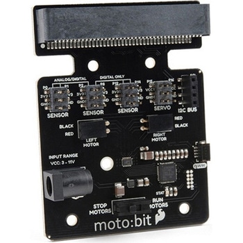 SparkFun moto:bit - micro:bit Carrier Board QwiicSPARKFUN
¥9,398税込¥10,338
1個
33日以内出荷
DescriptionThe SparkFun moto:bit is a fully loaded "carrier" board for the micro:bit that, when combined with the micro:bit, provides you with a fully functional robotics platform. The moto:bit offers a simple, beginner-friendly robotics controller capable of operating a basic robotics chassis. Onboard each moto:bit are multiple I/O pins, as well as a vertical Qwiic connector, capable of hooking up servos, sensors and other circuits. At the flip of the switch you can get your micro:bit moving!The moto:bit connects to the micro:bit via an updated SMD, edge connector at the top of the board, making setup easy. This creates a handy way to swap out micro:bits for programming, while still providing reliable connections to all of the different pins on the micro:bit. We have also included a basic barrel jack on the moto:bit that is capable of providing power to anything you connect to the carrier board.The micro:bit is a pocket-sized computer that lets you get creative with digital technology. Between the micro:bit and our shield-like bit boards you can do almost anything while coding, customizing and controlling your micro:bit from almost anywhere! You can use your micro:bit for all sorts of unique creations, from robots to musical instruments and more. At half the size of a credit card, this versatile board has vast potential!Note:The SparkFun moto:bit doesNOTinclude a micro:bit board. The micro:bit will need to be purchased separately.Get started with the moto:bit GuideFeaturesMore reliable Edge connector for easy use with the micro:bitFull H-Bridge for control of two motorsControl servo motorsVertical Qwiic ConnectorI2C port for extending functionalityPower and battery management onboard for the micro:bit
アズワン品番67-0422-89
 Poke Home Connector - 2-PinSPARKFUN
¥189税込¥208
1個
33日以内出荷
DescriptionPoke Home Connectors have been featured on a number of our boards over the last few years by providing a simple screw-terminal-type connector for easy wire connection purposes. Similar to screw terminals, Poke Home Connectors grasp a wire entered into the receiving area of the pin-out by pressing down on the small plastic strip at the end of the housing. Doing so raises the internal clamp and, upon release of the button secures the wire in place without any soldering required.Poke Home Connectors work better in environments with a lot of vibrations(i.e. automotive applications)or when a wire is expanding or contracting due to temperature cycling. Additionally, the tension in the connector is automatically adjusted to the wire gauge(assuming it is within the accepted wire thickness)as opposed to variances in tension when a user tightens the screw terminal.
アズワン品番67-0425-83
 SparkFun Inventor's Kit for micro:bit v2SPARKFUN
¥17,980税込¥19,778
1個
33日以内出荷
DescriptionThe SparkFun Inventor's Kit(SIK)for micro:bit v2 is a great way to get creative, connected and coding with the micro:bit. The SIK for micro:bit v2 provides not only the micro:bit v2 board but everything you need to hook up and experiment with multiple electronic circuits! With the SIK for micro:bit v2 you will be able to complete circuits that will teach you how to read sensors, move motors, build Bluetooth(R)devices and more.The SparkFun Inventor's Kit for micro:bit is the latest and greatest in single-board computer kits. Surrounding the micro:bit v2 SIK is one core philosophy --- that anyone can(and should)experiment with cutting-edge electronics in a fun and playful way without breaking the bank.The kit does not require any soldering and is recommended for all users, from beginners to engineers. We have provided a complete Experiment Guide in the Documents tab for you to check out now! If you have ever been interested in learning about electronics, or if you have used the original SparkFun Inventor's Kit and are looking for something new, the SIK for micro:bit is the perfect kit for you!The micro:bit is a pocket-sized computer that lets you get creative with digital technology. Between the micro:bit and our shield-like bit boards you can do almost anything while coding, customizing and controlling your micro:bit from almost anywhere! You can use your micro:bit for all sorts of unique creations, from robots to musical instruments and more. At half the size of a credit card, this versatile board has vast potential!ExamplesCircuit 0:Hello, micro:bit!Circuit 1:Blinking an LEDCircuit 2:Reading a PotentiometerCircuit 3:Reading a PhotoresistorCircuit 4:Driving an RGB LEDCircuit 5:Reading an SPDT SwitchCircuit 6:Reading a Button PressCircuit 7:Reading the Temperature SensorCircuit 8:Using a Servo MotorCircuit 9:Using a BuzzerCircuit 10:Using the AccelerometerCircuit 11:Using the Compass
アズワン品番67-0424-61
 Logitech K400 Plus Wireless Touch KeyboardSPARKFUN
¥16,980税込¥18,678
1個
33日以内出荷
DescriptionThe Logitech K400 Plus Wireless Touch Keyboard is a compact keyboard with an integrated touchpad that puts all your controls in a single device. Enjoy your entertainment without the clutter of multiple devices. Comfortable, quiet keys and a
アズワン品番67-0429-23
 SparkFun MicroMod Artemis ProcessorSPARKFUN
¥6,198税込¥6,818
1個
33日以内出荷
DescriptionLeveraging the ultra powerful Artemis Module, the SparkFun MicroMod Artemis Processor is the brain board of your dreams. With a Cortex-M4F with BLE 5.0 running up to 96MHz and with as low power as 6uA per MHz(less than 5mW), the M.2 MicroMod connector allows you to plug in a MicroMod Carrier Board with any number of peripherals. Let's have a look at what this processor board has to offer! If you need Machine Learning capabilities, Bluetooth, I2C functionality to connect to all our amazing Qwiic boards, and more the Artemis Processor is the perfect choice for your MicroMod Carrier Board.At the heart of SparkFun's Artemis Module is Ambiq Micro's Apollo3 processor, whose ultra-efficient ARM Cortex-M4F processor is spec'd to run TensorFlow Lite using only 6uA/MHz. We've routed two I2C buses, eight GPIO, dedicated digital, analog, and PWM pins, multiple SPI as well as QuadSPI, and Bluetooth to boot. You really can't go wrong with this processor. Grab one today, pick up a compatible carrier board, and get hacking!MicroMod is a modular interface ecosystem that connects a microcontroller "processor board" to various "carrier board" peripherals. Utilizing the M.2 standard, the MicroMod standard is designed to easily swap out processors on the fly. Pair a specialized carrier board for the project you need with your choice of compatible processor!Get Started with the MicroMod Artemis Processor GuideFeaturesArtemis General Features1M Flash / 384k RAM48MHz / 96MHz turbo available6uA/MHz(operates less than 5mW at full operation)48 GPIO - all interrupt capable31 PWM channelsBuilt in BLE radio and antenna10 ADC channels with 14-bit precision with up to 2.67 million samples per second effective continuous, multi-slot sampling rate2 channel differential ADC2 UARTs6 I2C buses6 SPI buses2/4/8-bit SPI busPDM interfaceI2S InterfaceSecure 'Smart Card' interfaceFCC/IC/CE Certified(ID Number 2ASW8-ART3MIS)Specific Peripherals made available on MicroMod Artemis:1x USB dedicated for programming and debug1x UART with flow control2x I2C1x SPI1x Quad-SPI8x Fast GPIO2x Digital Pins2x Analog Pins2x PWM1x Differential ADC pairStatus LEDVIN Level ADCAdditional peripherals are available but are shared on dedicated MicroMod pins.
アズワン品番67-0423-05
 LilyPad Sewable Electronics KitSPARKFUN
¥31,980税込¥35,178
1個
33日以内出荷
DescriptionThe LilyPad Sewable Electronics Kit lets you explore the wonderful world of electronic sewing(e-sewing)and e-textiles through a series of introductory projects using the LilyPad system. You'll learn how to sew basic circuits to light up LEDs, control them with buttons and switches and even experiment with a pre-programmed LilyMini circuit that reacts to ambient light levels. In addition to LilyPad LEDs and battery holders, the kit comes with two LilyPad ProtoSnap boards that let you explore the circuit before you sew the pieces into a project.The full-color LilyPad Sewable Electronics Kit Guide(included)contains step-by-step instructions for using LilyPad pieces to create four complete sewable circuit projects with conductive thread. Easy-to-follow diagrams and troubleshooting tips make this a great introductory resource for crafters and creatives.LilyPad is a wearable technology developed by Dr. Leah Buechley and cooperatively designed by Dr. Buechley and SparkFun. Each LilyPad component was creatively constructed with large sew tabs to allow for stitching into clothing. Various input, output, power and sensor boards are available. They're even washable!Note:A portion of this sale is given back to Dr. Buechley for continued development and education in e-textiles.Note:Due to the requirements of shipping the batteries in this kit, orders may take longer to process and therefore do not qualify for same-day shipping. Additionally, these batteries can not be shipped via Ground or Economy methods to Alaska or Hawaii. Sorry for any inconvenience this may cause.ExamplesSewable Electronics Projects:Project 1:Glowing PinProject 2:Illuminated MaskProject 3:Light-Up PlushProject 4:Night-Light Pennant
アズワン品番67-0424-05
 SparkFun Qwiic Scale - NAU7802SPARKFUN
¥5,698税込¥6,268
1個
33日以内出荷
DescriptionThe SparkFun Qwiic Scale is a small breakout board for the NAU7802 that allows you to easily read load cells to accurately measure the weight of an object. By connecting the board to your microcontroller you will be able to read the change
アズワン品番67-0426-97
 Panel Mount USB-B to Micro-B Cable - 6"SPARKFUN
¥1,198税込¥1,318
1個
欠品中
DescriptionThis panel mount USB-B(female)to micro-B(male)cable enables you to more easily enclose a project that contains a USB micro-B port. The cable is 6" in length and includes two 14mm M3 screws compatible with the cable's 3mm panel mount holes, spaced 28.5mm apart.
アズワン品番67-0420-57
 MI:pro Mountable Case for micro:bit V2SPARKFUN
¥1,998税込¥2,198
1個
33日以内出荷
DescriptionThe Mountable MI:pro is a simple and compact protective case for the micro:bit. This case has been specifically designed with portability and expansion in mind and is compatible with both the original micro:bit V1 and the micro:bit V2. These cases feature a three-layer construction style with ability to wall-mount the whole assembly onto any surface you want while still providing access to all buttons and ports on the micro:bit. Though these cases do feature wall-mountable tabs, the biggest benefit of using a case is to not accidentally short out the pads on the back of the micro:bit.Construction is simple, requiring only a small flathead screwdriver, and involves layering each plate on top of one another around the micro:bit and screwing it into place. Luckily, the MI:pro case enables easy access to the edge pins at the bottom of the micro:bit, allowing it to still be plugged into an edge connector found on many of our carrier boards. The only board that cannot be used in conjunction with the MI:pro case is the SparkFun gamer:bit due to its edge connector being located in the center of the board.Note:The MI:pro case only includes the parts found in the Includes Tab. This case does NOT include a micro:bit, power source or mounting screws. These items will need to be purchased separately.FeaturesDimensions:Length(minus the mounting brackets on the side):65mm.Length(with the mounting brackets on the side):91mm.Width:37mm.Depth(without screws):9mm.Depth(with screws):14mm.Provides excellent protection to the BBC micro:bit whilst allowing access to the bottom pins.Full access to the A and B buttons on the BBC micro:bit.The mounting points allow you to fix the micro:bit to a surface for sturdy and more permanent installations.Full access to pins and connections including the micro USB connector.Clear case material shows the on-board LEDs in perfect clarity.The case is compatible with versions 1 and 2 of the micro:bit.
アズワン品番67-0426-14
 Panel Mount USB Micro-B Extension Cable - 6"SPARKFUN
¥1,398税込¥1,538
1個
欠品中
DescriptionThis panel mount USB micro-B extension cable enables you to more easily enclose a project that contains a USB micro-B port. The cable is 6" in length and includes two 14mm M3 screws compatible with the cable's 3mm panel mount holes, spaced 16.5mm apart.
アズワン品番67-0420-58
 SparkFun Configurable OpAmp Board - TSH82SPARKFUN
¥2,298税込¥2,528
1個
欠品中
DescriptionThe SparkFun TSH82 Configurable OpAmp Board was designed to give you the best combination of performance and flexibility that we could achieve by giving you two gain stages, each one independently accessible on the header pins. Each stage is natively configured as an inverting amplifier that can also be strung together to expand the capabilities of the TSH82 from STMicroelectronics. With the use of the jumpers on the back of the board, you can configure each stage for non-inverting operation, differential input, and DC input coupling.Electrically speaking, both stages on this board are identical. The default configuration is inverting with a gain of -4.7 with a bandwidth of almost 10MHz. Input signals are AC coupled, possess an input impedance of 10K with a low frequency cutoff of 15.9Hz. Outputs are also DC coupled, so don't forget to add a capacitor to the output if you're running a single-ended supply and need to strip out the DC component. The board will also operate with a single-ended DC power supply of 4.5V to 12V, or a bipolar supply from +/-2.25V to +/-6V.On the back of the board you'll find 10 solder jumpers that can be used to change the board's performance, but nothing there needs to be changed to use it in it's default state.Get Started With the Configurable OpAmp Board Guide
アズワン品番67-0420-03
 SparkFun Power Delivery Board - USB-C QwiicSPARKFUN
¥8,998税込¥9,898
1個
33日以内出荷
DescriptionIt's time to effectively manage the power distribution into your project and with the SparkFun Power Delivery Board, you can! Traditional power adapters can provide a wide range of current but the voltage stays fixed at 5V. With the Spark
アズワン品番67-0422-93

 ナリカ")
 ナリカ")


(3種各4個セット) ナリカ")


 ナリカ")


