


絞り込み
ブランド
- SPARKFUN
- DIGILENT(1)
商品レビュー
- 以上(0)
- 以上(0)
- 以上(0)
- 以上(0)
価格
- 1,500円以下(3)
- 1,500-10,000円(4)
- 10,000-50,000円(7)
- 100,000円以上(3)
価格で絞り込む
出荷目安
- 当日
- 翌日以内
- 翌々日以内
- 3日以内
- 4日以内
当日・翌日以内・翌々日以内・3日以内・4日以内
その他
- 取扱い終了商品を除く
- 個人購入不可商品を除く

 MPLAB PICkit 4 In-Circuit DebuggerSPARKFUN
¥45,980税込¥50,578
1個
当日出荷
DescriptionThis is the PICkit 4, the official programmer from Microchip. The PICkit 4 allows debugging and programming of PIC(R), dsPIC(R), AVR, SAM and CEC flash microcontrollers and MPUs using the powerful graphical user interface of the MPLAB X Integrated Development Environment(IDE). The MPLAB PICkit 4 is connected to a PC using a high-speed 2.0 USB interface and can be connected to the target via an 8-pin Single In-Line(SIL)connector. The connector uses two device I/O pins and the reset line to implement in-circuit debugging and In-Circuit Serial Programming(TM)(ICSP(TM)). An additional micro SD card slot and the ability to be self-powered from the target means you can take your code with you and program on the go. Comes with a USB to micro-B USB cable.FeaturesPowered by a high-speed USB 2.0, no external power requiredReal-time executionMPLAB X IDE compatible(free copy included)Built-in over-voltage/short circuit monitorFirmware upgradeable from PC/web downloadFully enclosedTarget voltage of 1.20V to 5.5VCan supply up to 50mA of power to the targetMinimal current consumption at <100μA from targetDiagnostic LEDs(power, busy, error)Read/write program and data memory of microcontrollerErase of program memory space with verificationFreeze-peripherals at breakpoint8-pin single in-line header supports advanced interfaces such as 4-wire JTAG and Serial Wire Debug with streaming Data GatewayBackward compatible for demo boards, headers and target systems using 2-wire JTAG and ICSP
アズワン品番67-0425-08
 SparkFun XBee Explorer DongleSPARKFUN
¥9,298~税込¥10,228~特価
1個
当日出荷から33日以内出荷
DescriptionThis is the SparkFun XBee Explorer Dongle unit for the Digi XBee module line. With the XBee Explorer Dongle you can plug the unit directly into your USB port and have it act as a gateway between your computer and the XBee. No cables needed
仕様●項目1:USBドングル●項目2:無線ネットワーク、データー通信●項目4:XBee●項目7:XBeeアズワン品番67-0455-61
 DC Barrel Power Jack/Connector SMDSPARKFUN
¥699税込¥769
1個
欠品中
DescriptionThis is a common SMD barrel-type power jack for DC wall supplies. These are compatible with our DC wall supplies and have a 5.5mm jack, with a 2.1mm center pole diameter.
アズワン品番67-0425-10
 RF Link Transmitter - 315MHzSPARKFUN
¥1,698税込¥1,868
1個
33日以内出荷
DescriptionThese wireless transmitters work with our 315MHz receivers. They can easily fit into a breadboard and work well with microcontrollers to create a very simple wireless data link. Since these are only transmitters, they will only work communicating data one-way, you would need two pairs(of different frequencies)to act as a transmitter/receiver pair.Note:These modules are indiscriminate and will receive a fair amount of noise. Both the transmitter and receiver work at common frequencies and don't have IDs. Therefore, a method of filtering this noise and pairing transmitter and receiver will be necessary. The example code below shows such an example for basic operation. Please refer to the example code and links below for ways to accomplish a robust wireless data link.Features315MHz500ft range(given perfect conditions)4800bps data rate5V supply voltage
アズワン品番67-0430-46
 RF Link Receiver - 4800bps 315MHzSPARKFUN
¥1,998税込¥2,198
1個
33日以内出荷
DescriptionThese wireless receivers work with our 315MHz transmitters. They can easily fit into a breadboard and work well with microcontrollers to create a very simple wireless data link. Since these are only receivers, they will only work communicating data one-way, you would need two pairs(of different frequencies)to act as a transmitter/receiver pair.Note:These modules are indiscriminate and will receive a fair amount of noise. Both the transmitter and receiver work at common frequencies and don't have IDs. Therefore, a method of filtering this noise and pairing transmitter and receiver will be necessary. The example code below shows such an example for basic operation. Please refer to the example code and links below for ways to accomplish a robust wireless data link.Note:These receivers are almost identical to the RF link 434MHz receiver. SparkFun does everything in our power to make sure you receive the product you requested. However, if you are concerned you may have received the incorrect product you can verify which version receiver this is by running a simple test circuit.Features315 MHz500ft range(given perfect conditions)4800bps data rate5V supply voltage
アズワン品番67-0430-44
 XBee 3 Pro Module - U.FL AntennaSPARKFUN
¥12,980税込¥14,278
1個
33日以内出荷
DescriptionAfter years of popularity with the XBee Series 1 and XBee Series 2 Pro Modules, we now have the XBee Series 3 Pro which brings the best of both worlds. XBee 3 not only handles 802.15.4, and ZigBee, but also BLE protocols and you can now talk to the modules over UART or SPI as well. With a 300ft indoor range, or 2mile outdoor/line-of-sight range, you can set up a mesh network to talk to or communicate with various devices around your house, work, or other area.This module has the familiar XBee package while sporting a U.FL connector to add an antenna. You also get a built in microcontroller so you can also configure and program the modules using MicroPython as well as Digi's XCTU software. With a HCS08 CPU running at up to 50.33MHz, 15x digital I/O pins, and 4x 10-bit ADC pins these modules can even hold their own as a microcontroller.Note:While these are backwards compatible in many ways with the XBee 1s and 2s, they are not completely compatible. Please see documentation for differences if you plan on adding these to an existing project.FeaturesRF 250Kbps, Serial 1Mbps300ft(indoor)to 2 mile(outdoor)rangeTransmit power +19dBM @ 135mAReceiver Sensitivity -103dBm @ 15mA4x 10-bit ADC inputs15x Digital I/O pinsHCS08 CPU at up to 50.33MHz128/256 bit AES Encryption2.1V to 3.6V operating voltage1.7 μA power-down currentBuilt in RS-485 supportAT command or API frame supportFCC Certified
アズワン品番67-0429-52
 XBee 3 Pro Module - RP-SMA AntennaSPARKFUN
¥11,980税込¥13,178
1個
33日以内出荷
DescriptionAfter years of popularity with the XBee Series 1 and XBee Series 2 Pro Modules, we now have the XBee Series 3 Pro which brings the best of both worlds. XBee 3 not only handles 802.15.4, and ZigBee, but also BLE protocols and you can now talk to the modules over UART or SPI as well. With a 300ft indoor range, or 2mile outdoor/line-of-sight range, you can set up a mesh network to talk to or communicate with various devices around your house, work, or other area.This module has the familiar XBee package while sporting a connector to add an RP-SMA antenna. You also get a built in microcontroller so you can also configure and program the modules using MicroPython as well as Digi's XCTU software. With a HCS08 CPU running at up to 50.33MHz, 15x digital I/O pins, and 4x 10-bit ADC pins these modules can even hold their own as a microcontroller.Note:While these are backwards compatible in many ways with the XBee 1s and 2s, they are not completely compatible. Please see documentation for differences if you plan on adding these to an existing project.FeaturesRF 250Kbps, Serial 1Mbps300ft(indoor)to 2mile(outdoor)rangeTransmit power +19dBM @ 135mAReceiver Sensitivity -103dBm @ 15mA4x 10-bit ADC inputs15x Digital I/O pinsHCS08 CPU at up to 50.33MHz128/256 bit AES Encryption2.1V to 3.6V operating voltage1.7 μA power-down currentBuilt in RS-485 supportAT command or API frame supportFCC Certified
アズワン品番67-0429-54
 Qwiic Cable - Grove Adapter 100mmSPARKFUN
¥709税込¥780
1個
欠品中
DescriptionWith the SparkFun Qwiic Connect System expanding every day, we want to make sure it becomes as accessible as possible but we understand there are other systems that can compliment it out there. The Qwiic to Grove Adapter Cable allows interoperability between the SparkFun Qwiic Connect System and the I2C based Grove boards from Seeed Studio. Now you can plug Seeed Studio boards you may have onto the Qwiic bus or you can use this cable to introduce Qwiic sensors, inputs, and outputs into your Grove system.Note:The Grove system has a variety of different signal systems that use the same connector. This cableonlyworks with the I2C variety.The SparkFun Qwiic connect system is an ecosystem of I2C sensors, actuators, shields and cables that make prototyping faster and less prone to error. All Qwiic-enabled boards use a common 1mm pitch, 4-pin JST connector. This reduces the amount of required PCB space, and polarized connections mean you can't hook it up wrong.FeaturesLength:100mm
アズワン品番67-0425-61
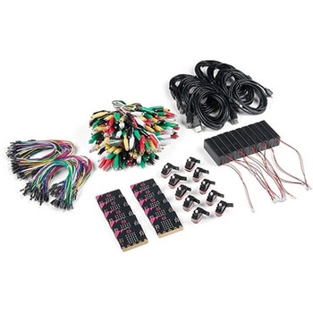
 LilyPad Sewable Electronics KitSPARKFUN
¥31,980税込¥35,178
1個
33日以内出荷
DescriptionThe LilyPad Sewable Electronics Kit lets you explore the wonderful world of electronic sewing(e-sewing)and e-textiles through a series of introductory projects using the LilyPad system. You'll learn how to sew basic circuits to light up LEDs, control them with buttons and switches and even experiment with a pre-programmed LilyMini circuit that reacts to ambient light levels. In addition to LilyPad LEDs and battery holders, the kit comes with two LilyPad ProtoSnap boards that let you explore the circuit before you sew the pieces into a project.The full-color LilyPad Sewable Electronics Kit Guide(included)contains step-by-step instructions for using LilyPad pieces to create four complete sewable circuit projects with conductive thread. Easy-to-follow diagrams and troubleshooting tips make this a great introductory resource for crafters and creatives.LilyPad is a wearable technology developed by Dr. Leah Buechley and cooperatively designed by Dr. Buechley and SparkFun. Each LilyPad component was creatively constructed with large sew tabs to allow for stitching into clothing. Various input, output, power and sensor boards are available. They're even washable!Note:A portion of this sale is given back to Dr. Buechley for continued development and education in e-textiles.Note:Due to the requirements of shipping the batteries in this kit, orders may take longer to process and therefore do not qualify for same-day shipping. Additionally, these batteries can not be shipped via Ground or Economy methods to Alaska or Hawaii. Sorry for any inconvenience this may cause.ExamplesSewable Electronics Projects:Project 1:Glowing PinProject 2:Illuminated MaskProject 3:Light-Up PlushProject 4:Night-Light Pennant
アズワン品番67-0424-05
 SparkFun GPS Breakout - NEO-M9N, SMA QwiicSPARKFUN
¥22,980税込¥25,278
1個
33日以内出荷
DescriptionThe SparkFun NEO-M9N GPS Breakout is a high quality GPS board with equally impressive configuration options including SMA. The NEO-M9N module is a 92-channel u-blox M9 engine GNSS receiver, meaning it can receive signals from the GPS, GLONASS, Galileo, and BeiDou constellations with ~1.5 meter accuracy. This breakout supports concurrent reception of four GNSS. This maximizes position accuracy in challenging conditions increasing, precision and decreases lock time; and thanks to the onboard rechargeable battery, you'll have backup power enabling the GPS to get a hot lock within seconds! Additionally, this u-blox receiver supports I2C(u-blox calls this Display Data Channel)which makes it perfect for the Qwiic compatibility so we don't have to use up our precious UART ports. Utilizing our handy Qwiic system, no soldering is required to connect it to the rest of your system. However, we still have broken out 0.1"-spaced pins in case you prefer to use a breadboard.The NEO-M9N module detects jamming and spoofing events and can report them to the host, so that the system can react to such events. A SAW(Surface Acoustic Wave)filter combined with an LNA(Low Noise Amplifier)in the RF path is integrated into the NEO-M9N module which allows normal operation even under strong RF interferences.U-blox based GPS products are configurable using the popular, but dense, windows program called u-center. Plenty of different functions can be configured on the NEO-M9N:baud rates, update rates, geofencing, spoofing detection, external interrupts, SBAS/D-GPS, etc. All of this can be done within the SparkFun Arduino Library!The SparkFun NEO-M9N GPS Breakout is also equipped with an on-board rechargeable battery that provides power to the RTC on the NEO-M9N. This reduces the time-to-first fix from a cold start(~24s)to a hot start(~2s). The battery will maintain RTC and GNSS orbit data without being connected to power for plenty of time.This product requires an antenna:Be sure to check out the related products/hookup accessories and pick a suitable SMA antenna for your project.The SparkFun Qwiic Connect System is an ecosystem of I2C sensors, actuators, shields and cables that make prototyping faster and less prone to error. All Qwiic-enabled boards use a common 1mm pitch, 4-pin JST connector. This reduces the amount of required PCB space, and polarized connections mean you can't hook it up wrong.The NEO-M9N GPS Breakout can also be automatically detected, scanned, configured, and logged using the OpenLog Artemis datalogger system. No programming, soldering, or setup required!Get Started With the SparkFun NEO-M9N GPS GuideFeaturesIntegrated SMA connector for use with antenna of your choice92-Channel GNSS Receiver1.5m Horizontal Accuracy25Hz Max Update Rate(four concurrent GNSS)Time-To-First-Fix:Cold:24sHot:2sMax Altitude:80,000mMax G:≦4Max Velocity:500m/sVelocity Accuracy:0.05m/sHeading Accuracy:0.3 degreesTime Pulse Accuracy:30ns3.3V VCC and I/OCurrent Consumption:~31mA Tracking GPS+GLONASSSoftware ConfigurableGeofencingOdometerSpoofing DetectionExternal InterruptPin ControlLow Power ModeMany others!Supports NMEA, UBX, and RTCM protocols over UART or I2C interfaces
アズワン品番67-0423-87
 SparkFun Inventor's Kit for micro:bit v2 Lab PackSPARKFUN
¥159,800税込¥175,780
1個
33日以内出荷
DescriptionThe SparkFun Inventor's Kit for micro:bit v2 Lab Pack includes 10 complete micro:bit v2 Inventor's Kits, an SIK Refill Pack and 25 AAA-sized batteries to get your students started in the world of electronics. The SIKs inside the Lab Pack have everything you need, including micro:bit v2s, connector breakouts, breadboards and all the cables and accessories to hook up all the projects listed in our online Experiment Guide.The kit does not require any soldering and is recommended for all users, from beginners to engineering students. We have provided a complete Experiment Guide in the Documents tab for you to check out now! If you are new to teaching electronics or have taught with the original SparkFun Inventor's Kit and are looking for something new, the SIK for micro:bit v2 is the perfect kit for you!SparkFun packages everything educators need to get started with this platform in a variety of classroom and makerspace settings with diverse student populations. The hardware boards, cables and extra parts come pre-packaged, and our online support materials --- including an online Experiment Guide(to be updated)--- help you bring the power of the open source community to your classroom. Examples and curriculum materials are available from SparkFun and Arduino, as well as from other educators involved in this growing maker movement.The micro:bit is a pocket-sized computer that lets you get creative with digital technology. Between the micro:bit and our shield-like bit boards you can do almost anything while coding, customizing and controlling your micro:bit from almost anywhere! You can use your micro:bit for all sorts of unique creations, from robots to musical instruments and more. At half the size of a credit card, this versatile board has vast potential!
アズワン品番67-0424-93
 SparkFun RedBoard ArtemisSPARKFUN
¥7,698税込¥8,468
1個
33日以内出荷
DescriptionThink of the RedBoard Artemis as just another Arduino... That has BLE. And one megabyte of flash. And runs at less than 1mA. Oh, and it can run TensorFlow models. Ya, that too. The RedBoard Artemis takes the incredibly powerful Artemis module from SparkFun and wraps it up in an easy to use and familiar Uno footprint. We've written an Arduino core from scratch to make programming the Artemis as familiar asSerial.begin(9600). Time-to-first-blink is less than five minutes.The RedBoard Artemis has the improved power conditioning and USB to serial that we've refined over the years on our RedBoard line of products. A modern USB-C connector makes programming easy. A Qwiic connector makes I2C easy. The RedBoard Artemis is fully compatible with SparkFun's Arduino core and can be programmed easily under the Arduino IDE. We've exposed the JTAG connector for more advanced users who prefer to use the power and speed of professional tools. We've added a digital MEMS microphone for folks wanting to experiment with always-on voice commands with TensorFlow and machine learning. We've even added a convenient jumper to measure current consumption for low power testing.With 1MB flash and 384k RAM you'll have plenty of room for your sketches. The on-board Artemis module runs at 48MHz with a 96MHz turbo mode available and with Bluetooth to boot!The SparkFun RedBoard Artemis is a great platform to 'kick the tires' of this amazing module. If you're interesting in testing out the full capabilities of the SparkFun Artemis module or if you're looking for more compact solution, be sure to checkout our ATP and Nano versions of the Artemis line.Get Started With the SparkFun Artemis RedBoard GuideFeaturesArduino Uno R3 Footprint1M Flash / 384k RAM48MHz / 96MHz turbo available24 GPIO - all interrupt capable21 PWM channelsBuilt in BLE radio10 ADC channels with 14-bit precision2 UARTs6 I2C buses4 SPI busesPDM InterfaceI2S InterfaceQwiic Connector
アズワン品番67-0422-82
 SparkFun Load Sensor CombinatorSPARKFUN
¥839税込¥923
1個
欠品中
DescriptionThe SparkFun Load Sensor Combinator is a bare PCB that combines four load sensors into a standard four-wire Wheatstone bridge configuration. If you open up an electronic bathroom scale, you'll find a large rat's nest of wires. The Load Sensor Combinator was created to combine the 12 wires found in a bathroom scale into the standard four-wire Wheatstone bridge configuration.This version of the SparkFun Load Sensor Combinator features a few changes that you specifically asked for! We updated the silk on the breakout to read "C/+/-" instead of "R/W/B" and moved the temperature sensor connector away from the standoff hole.You can either use four individual load sensors or simply purchase an off-the-shelf bathroom scale and hack the combinator into it rather than trying to design a base to properly mount four load sensors.This board works great with our Load Cell Amplifier breakout board; the five pins on the edge of the combinator line up directly to the five pins on the amplifier.If your amplifier and supporting electronics are more than a few inches away from the scale, an RJ45 footprint is provided. The four Wheatstone pins(E+/E-/S+/S-)as well as the shield pin are connected to twisted pairs within a standard cheap Ethernet cable. This allows the amplifier board to be placed many feet away from the scale itself.The combinator board also includes a footprint for the DS18B20 one-wire temperature sensor. This allows the user to gather the temperature of the scale in case there is a large variance between the scale and the amplifier. These three pins are accessed through the RJ45 connection as well, allowing remote temperature readings to be gathered over one twisted pair Ethernet cable.NOTE:The SparkFun Load Sensor Combinator will only work with 3 wire load sensors, it is not compatible with 4 wire load cells.
アズワン品番67-0419-93
 SparkFun Educator Lab Pack for micro:bit v2SPARKFUN
¥109,800税込¥120,780
1個
33日以内出荷
DescriptionThe micro:bit v2 Educator's Lab Pack includes 10 micro:bit v2 boards and everything you need to get you started with the new learning platform. The Lab Pack has everything you need, including micro:bits, cables, battery packs and a few parts to experiment with. This package provides an easy way to introduce your students to the micro:bit without any difficulty or parts hunting.SparkFun packages everything educators need to get started with the micro:bit in a variety of classroom settings and learning environments. The hardware boards, cables and extra parts come pre-packaged. Examples and curriculum materials are available from SparkFun and micro:bit, as well as from other educators involved in this growing maker education movement.Lab Packs are your classroom entry point. By combining our kits, popular boards and other educational tools with support materials(to be updated), SparkFun brings all the power of the open source community to the classroom. We've also updated the battery pack to be closer to what is in other micro:bit kits. It now requires 2xAAA batteries.The micro:bit is a pocket-sized computer that lets you get creative with digital technology. Between the micro:bit and our shield-like bit boards you can do almost anything while coding, customizing and controlling your micro:bit from almost anywhere! You can use your micro:bit for all sorts of unique creations, from robots to musical instruments and more. At half the size of a credit card, this versatile board has vast potential!FeaturesMicro:bit 2.0:64 MHz Arm Cortex-M4 with FPU512KB Flash128KB RAM5x5 Red LED ArrayTwo Programmable Buttons, one touch sensitive logoMEMS microphone and LED indicatorOnboard Light, Compass, Accelerometer, Temp Sensors and Speaker2.4 Ghz Micro:bit Radio/BLE 5.0 Smart Antenna25-pin Edge Connector4 dedicated GPIO, PWM, i2c, SPI, and ext. powerThree Digital/Analog Input/Output RingsTwo Power Rings --- 3V and GNDDedcated I2C bus for peripheralsMicroUSB Connector(5V)JST-PH Battery Connector(NotJST-XH)(3V)Power/reset Button with Status LED200 mA available for accessoriesProgram with C++, MakeCode, Python, Scratch
アズワン品番67-0424-92
 SparkFun Qwiic Dual Solid State RelaySPARKFUN
¥39,980税込¥43,978
1個
33日以内出荷
DescriptionThe SparkFun Qwiic Dual Solid State Relay is a power delivery board that allows users to switch two AC loads from a low power microcontroller using the SparkFun Qwiic connect system. The board features two 25A/250VAC solid state relays that utilize the Zero Cross Trigger method so you can toggle two loads on a 60Hz AC carrier signal on and off up to 120 times per second!An ATTiny84 acts as the "brain" of the SparkFun Qwiic Dual Solid Relay to accept I2C commands to toggle the two relays as well as a few other special commands. The I2C address of the ATtiny84A is software configurable so, if you have a seriously big power project in mind, you could daisy chain over 100 Qwiic Dual Solid State Relays.Messing with such high voltage is dangerous! We've included many safety precautions onto the PCB including ground isolation between the relay and other circuitry and a milled out area isolating each side of AC. However, with all the safety precautions included with the SparkFun Qwiic Dual Solid State Relay, this is still a power accessory for users who are experienced around, and knowledgeable about high AC voltage. If you're not comfortable with handling AC voltage in this way, you may want to check out the IoT Power Relay instead.Note:The relays are rated for a max of 25A with forced air cooling. If you do not have forced air cooling, 10A max through the relays is recommended.The SparkFun Qwiic connect system is an ecosystem of I2C sensors, actuators, shields and cables that make prototyping faster and less prone to error. All Qwiic-enabled boards use a common 1mm pitch, 4-pin JST connector. This reduces the amount of required PCB space, and polarized connections mean you can't hook it up wrong.Get Started with the SparkFun Qwiic Dual Solid State Relay GuideFeaturesOperating Voltage:2.5-3.6V(3.3V recommended)I2C Address:0x0A(Default)0x0B(Alternate via jumper select)Load Voltage Range:12-280VACMax Current(Through Relay):25A(240VAC with forced air cooling)Zero Cross TriggerNormally Open Circuit Only2x Qwiic Connector
アズワン品番67-0421-58
 PureThermal Mini Pro JST-SR with FLIR Lepton 3.5SPARKFUN
¥129,800税込¥142,780
1個
38日以内出荷
DescriptionThe new PureThermal Mini Pro JST-SR with Thermal by FLIR is a hackable thermal camera for the FLIR Lepton thermal imaging camera core. Just like its PureThermal 2 predecessor, it ships pre-configured to operate as a plug-and-play UVC 1.0 USB thermal webcam that will work with standard webcam and video apps on all major platforms using a JST-SR to USB Cable, or your own custom cable. For developers, its reference firmware and viewer software are open source.It has multiple connection options such as solder straight to the board or a custom cable using the JST-SR port. The PTMini Pro also features four mounting holes, less complex circuitry, and perhaps best of all, USB DFU. This is a development kit ready to be embedded into a production system.Each board comes with a FLIR Lepton 3.5.The FLIR Lepton(R)is a radiometric-capable LWIR camera solution that is smaller than a dime, fits inside a smartphone, and is one tenth the cost of traditional IR cameras. Using focal plane arrays of either 160x120 or 80x60 active pixels, Lepton easily integrates into native mobile-devices and other electronics as an IR sensor or thermal imager. The radiometric Lepton captures accurate, calibrated, and noncontact temperature data in every pixel of each image.FeaturesPureThermal:Compatible with all production FLIR Leptons, including radiometric 2.5 and 3.5 cores9 Hz color video over usb using the USB UVC classSTM32F412 ARM microprocessor - execute on-board image processing without need for an external systemOpen source reference firmware:GroupGets PureThermal GithubWorks with GetThermal - our custom open source thermal video display software for macOS and Linux with radiometric supportDFU over USB using a JST-SR port to USB cable, or a modified USB cable and the through holes.Four mounting holesCompact form-factor ready to be embedded into production systemsFLIR Lepton 3.5:Thermal sensitivity:< 50 mK(0.050℃)Spectral Range:8 - 14 microns(nominal)Long Wave Infrared(LWIR)Resolution:160h×120v pixelsRadiometric Accuracy - High Gain Mode:Greater of +/- 5℃ or 5%(typical); Low Gain Mode:Greater of +/- 10℃ or 10%(typical)Scene Dynamic Range - High Gain Mode:-10° to +140℃; Low Gain Mode:-10° to +400℃(at room temperature), -10° to +450℃(typical)Pixel Size:12 micrometersFrame Rate:8.7 Hz(effective)Output Format:User-selectable 14-bit, 8-bit(AGC applied), or 24-bit RGB(AGC and colorization applied)Horizontal Field of View(HFOV):57°Lens Type:f/1.1Size(w×l×h):10.50×12.70×7.14 mmWeight:0.9 gramsPower Consumption:150 mW typical, 650 mW during shutter event, 5mW standbyOptimum Operating Temperature Range:-10℃ to + 80℃
アズワン品番67-0423-44
『オフィスサプライ』には他にこんなカテゴリがあります

")


