



カテゴリ
- すべてのカテゴリ
- オフィスサプライ
- 学童・教育用品
- 理科/技術/科学工作(8)
- 学童・教育用品
- オフィスサプライ
絞り込み
ブランド

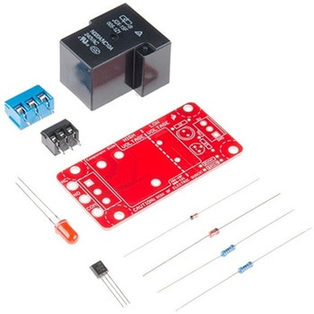
SparkFun Beefcake Relay Control Kit Ver. 2.0
SPARKFUN¥3,198税込¥3,5181個33日以内出荷Description。Your 5V system can wield great power with this big, beefy relay board. How does 10A on the NC contacts and 20A on the NO contacts at 220VAC sound? The SparkFun Beefcake Relay Control Kit contains all the parts you need to get your high-power load under control. Only minimal assembly is required!。The heart of the board is sealed, SPDT 20A/10A Relay. The relay is controlled by 5V logic through transistor, and an LED tells you when the relay is closed. This is kit, so it comes as through-hole parts with assembly required, which makes for some nice soldering practice. Screw terminal connectors on either side of the board make it easy to incorporate into your project.。There are some pretty beefy traces connecting the relay to the load pins, but the 3-pin terminals are only rated for 15A max! If you plan on connecting larger load, you'll need to solder directly to the board. As always with high current and voltage, play it safe and use your judgment when deciding how much of load you want to put on board -- in open airflow the PCB can handle the full 20A for few minutes at time, but in an enclosed area heat can build up.。Note:Please keep in mind that this board is really meant for someone with experience and good knowledge of electricity. If you're uncomfortable soldering or dealing with high voltage, please check out the IoT Power Relay. The IoT Power Relay is fully enclosed, making it lot safer.。Get Started With the Beefcake Hookup Assembly Guide。Features。Voltage Rating:220VAC/28VDC。VCC requirements:4-6V, 150mA capable。SPDT pins exposed(Form C)。14 AWG screw terminals for relay connections.。10 AWG solder lugs for relay connections.。Flyback diode included。Zener recovery diode included(decreases turn-off time)。Heavy oz. copper on PCBアズワン品番67-0424-03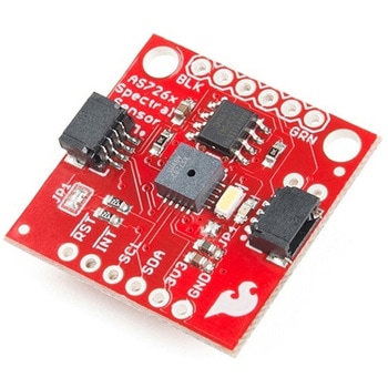
SparkFun Spectral Sensor Breakout - AS7263 NIR Qwiic
SPARKFUN¥9,998税込¥10,9981個33日以内出荷Description。The SparkFun AS7263 Near Infrared(NIR)Spectral Sensor Breakout brings spectroscopy to the palm of your hand, making it easier than ever to measure and characterize how different materials absorb and reflect different wavelengths of light. The AS7263 Breakout is unique in its ability to communicate by both an I2C interface and serial interface using AT commands. Hookup is easy, thanks to the Qwiic connectors attached to the board --- simply plug one end of the Qwiic cable into the breakout and the other into one of the Qwiic shields, then stack the board on a development board. You'll be ready to upload a sketch to start taking spectroscopy measurements in no time.。The AS7263 spectrometer detects wavelengths in the visible range at 610, 680, 730, 760, 810 and 860nm of light, each with 20nm of full-width half-max detection. The board also has multiple ways for you to illuminate objects that you will try to measure for a more accurate spectroscopy reading. There is an onboard LED that has been picked out specifically for this task, as well as two pins to solder your own LED into.。Note:The I2C address of the AS7263 is 0x49 and is hardware defined. A multiplexer/Mux is required to communicate to multiple AS7263 sensors on a single bus. If you need to use more than one AS7263 sensor consider using the Qwiic Mux Breakout.。The SparkFun Qwiic Connect System is an ecosystem of I2C sensors, actuators, shields and cables that make prototyping faster and less prone to error. All Qwiic-enabled boards use a common 1mm pitch, 4-pin JST connector. This reduces the amount of required PCB space, and polarized connections mean you can't hook it up wrong.。Get Started with the SparkFun AS726X Spectral Sensor Breakout Guide。Features。6 near-IR channels:610nm, 680nm, 730nm, 760nm, 810nm and 860nm, each with 20nm FWHM。NIR filter set realized by silicon interference filters。16-bit ADC with digital access。Programmable LED drivers。2.7V to 3.6V with I2C interface。2x Qwiic connectorsアズワン品番67-0426-70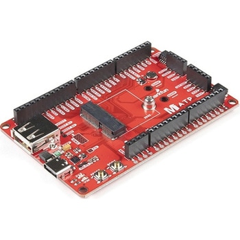
SparkFun MicroMod ATP Carrier Board
SPARKFUN¥6,298税込¥6,9281個33日以内出荷Description。Access all the pins(i.e. ATP)of the MicroMod Processor Boards with the SparkFun MicroMod ATP Carrier Board! This board breaks out the MicroMod Processor Board's pins on the M.2 connector to 0.1" spaced female headers and PTH pads on the edge of the board. This Carrier Board is great if you're interested in testing out different MicroMod Processor Boards for your application.。A modern USB-C connector makes programming easy. In addition to the pins broken out, two separate Qwiic-enabled I2C ports allow you to easily daisy chain Qwiic-enabled devices. We've exposed the SWD pins for more advanced users who prefer to use the power and speed of professional tools. A USB-A connector is provided for Processor Boards that have USB Host support. A backup battery is provided for processor boards with RTC. If you need a "lot" of GPIO with a simple-to-program, ready for market module, the ATP is the fix you need. We've even added a convenient jumper to measure the current consumption for low power testing.。MicroMod is a modular interface ecosystem that connects a microcontroller "processor board" to various "carrier board" peripherals. Utilizing the M.2 standard, the MicroMod standard is designed to easily swap out processors on the fly. Pair a specialized carrier board for the project you need with your choice of compatible processor!。Get Started with the MicroMod ATP Carrier Board Guide。Features。M.2 Connector。Operating Voltage Range。~3.3V to 6.0V(via VIN to AP7361C 3.3V Voltage Regulator)。3.3V(via 3V3)。Ports [1]。1x USB type C。1x USB type A Host。2x Qwiic Enabled I2C。1x CAN。1x I2S。2x SPI。2x UARTs。2x Dedicated Analog Pins。2x Dedicated PWM Pins。2x Dedicated Digital Pins。12x General Purpose Input Output Pins。1x SWD 2x5 header。1mAh battery backup for RTC。Buttons。Reset。Boot。LEDs。Power。3.3V。Phillips #0 M2.5x3mm screw included。[1] Note:Depending on the design of the Processor Board, not all the pins may be accessible.アズワン品番67-0423-18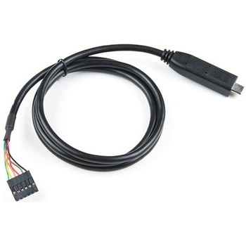
FTDI to USB-C Cable - 5V VCC-3.3V I/O
SPARKFUN¥7,998税込¥8,7981個33日以内出荷。Description。USB C is quickly becoming more and more prominent in the maker community because, let's be honest, who likes trying three times to insert USB into a port? This FTDI cable is a USB C to Serial converter which allows for a simple way to connect TTL interface devices to USB. Each 26AWG cable is one meter in length with the USB C side protected by a 2in enclosure.。The FTDI cable is designed around an RS232, which is housed in a USB C connector. The other side of the cable is terminated with a 0.1" pitch, 6-pin connector with the following pinout:RTS(Green), RX(Yellow), TX(Orange), VCC 5V(Red), CTS(Brown), GND(Black). This FTDI to USB C Cable is also capable of handling high voltages up to 300V max.。There are pros and cons to the FTDI Cable vs the FTDI Basic. The FTDI Basic has great LED indicators, but requires a Mini-B cable. The FTDI Cable is well protected against the elements, but is large and cannot be embedded into a project as easily. The FTDI Basic uses DTR to cause a hardware reset where the FTDI cable uses the RTS signal.アズワン品番67-0420-42
Actuonix PQ12-100-6-R Micro-Actuator
SPARKFUN¥47,980税込¥52,7781個33日以内出荷Description。The PQ12 series of micro linear actuators are ideal for applications requiring precise positioning and compact size. Weighing in at just 22 grams, the PQ12 is incredibly light as well as compact. The affordably-priced PQ12 is the most powerful actuator of it's size. This is why it has become a popular choice for OEM manufacturers as well as Arduino and RC hobbyists. Some industries where the PQ12 are in use include:prosthetics, robotics, medical, simulation.。The PQ12-R series of linear servos operate as a direct replacement for standard rotary servos. They use the same standard 3 wire connector, ground power and control. Regardless of how you drive your servos, be it with an RC receiver, an Arduino board, or a VEX micro-controller, the PQ12-R servo will function in place of a regular servo, but with the added benefit of providing linear motion. The PQ12-R is available in a 20mm stroke coupled with gear ratio options of 30:1, 63:1 and 100:1 cover a large variety of applications.。The PQ12-100-6-R has:a 100:1 gear ratio for maximum lifting force; 6VDC operating voltage; and a servo(PWM)interface. This powerful little actuator can lift 50N(~5kg)!。The datasheet doesn't mention a minimum operating voltage, but we've tested this actuator at 5VDC and it seems to work just fine. The maximum force and movement speed are reduced of course.。Features。Gearing Option:100:1。Peak Power Point:40N @ 6mm/s。Peak Efficiency Point:20N @ 8mm/s。Max Speed(no load):10mm/s。Max Force(lifted):50N。Max Side Load:10N。Back Drive Force:35N。Stroke:20 mm。Input Voltage:6 VDC。Stall Current:550mA @ 6V。Mass:22g。Operating Temperature -10℃ to +50℃。Positional Repeatability:±0.1mm。Mechanical Backlash:0.25 mm。Audible Noise:55dB @ 45cm。Ingress Protection:IP-54。Maximum Duty Cycle:20%。PWM(Servo)signal:Fully retracted:2.0ms @ 50Hz。Fully extended:1.0ms @ 50Hzアズワン品番67-0426-44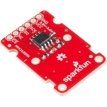
SparkFun Thermocouple Breakout - MAX31855K
SPARKFUN¥6,198税込¥6,8181個33日以内出荷Description。The SparkFun MAX31855K Thermocouple Breakout is a simple 14-bit resolution, SPI-compatible, serial interface thermocouple digitizer that makes reading a wide range of temperatures possible. A thermocouple works by taking two wires made of dissimilar metals, connecting them at the two ends, and making a temperature gradient between one end and the other(a 'hot' end and a 'cold' one). Once this is achieved, a voltage potential is formed and current flows. The SparkFun Thermocouple Breakout takes a standard Type-K thermocouple in one end, digitizes the temperature measured and sends that data out the other end via a SPI interface, thereby interpreting the data and translating it for you to read!。With the SparkFun Thermocouple Breakout, the thermocouple's hot junction can be read from -200℃ to +700℃ with an accuracy of ±2℃ while the cold junction, inside the MAX31855K, can only range from -20℃ to +85℃ while maintaining ±2℃ accuracy. The MAX31855K constantly measures the temperature of the cold junction using an internal temperature-sensing diode. The MAX31855K requires a power source from +3.0V to +3.6V(+3.0V nominal)and only draws 1.5mA maximum.。The Thermocouple Breakout is designed to accept a standard thermocouple connector, for convenience and compatibility with probes you may already own. These connectors aren't necessary, and you could solder a thermocouple directly into the through-holes labeled '+' and '-'. If you decide to solder the thermocouple directly to the breakout board, it is recommended that the thermocouple be mounted for strain relief to avoid breaking the thin wires. Notches for a zip-tie or wire wrapping have been provided in the PCB opposite the header for this purpose.。Features。14-bit Resolution。SPI-Compatible, Serial Interface。-200℃ to +700℃ Temperature Reading with ±2℃ Accuracy。3.0V to 3.6V(+3.0V nominal)Required。Accepts Type-K Thermocoupleアズワン品番67-0426-49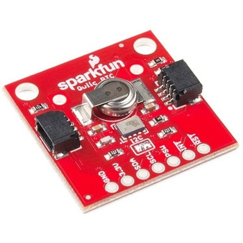
SparkFun Real Time Clock Module - RV-1805 Qwiic
SPARKFUN¥7,798税込¥8,5781個33日以内出荷Description。Get with the times, already! This SparkFun Real Time Clock(RTC)Module is a Qwiic-enabled breakout board for the RV-1805 chipset. The RTC is ultra-low power(running at only about 22nA in its lowest power setting)so it can use a supercapacitor for backup power instead of a normal battery. This means you get plenty of charge and discharge cycles without any degradation to the "battery." To make it even easier to get your readings, all communication is enacted exclusively via I2C, utilizing our handy Qwiic system so no soldering is required to connect it to the rest of your system. However, we still have broken out 0.1"-spaced pins in case you prefer to use a breadboard.。This RTC module's built in RV-1805 has not one, but two internal oscillators:a 32.768kHz tuning fork crystal and a low power RC based oscillator and can automatically switch between the two using the more precise crystal to correct the RC oscillator every few minutes. This feature allows the module to maintain a very accurate date and time with the worst case being +/- about three minutes over a year. The RV-1805 also has a built in trickle charger so as soon as the RTC is connected to power the it will be fully charged in under 10 minutes and has the ability to switch power to other systems allowing it to directly turn on or off a power hungry device such as a microcontroller or RF engine.。There is also the option to add a battery to the board if the supercapacitor just isn't going keep your project powered long enough(keep in mind, the supercap can hypothetically make the board keep time for around 35 days), you can solder on an external battery. That means you can let board sit with no power or connection to the outside world and the current hour/minute/second/date will be maintained.。Note:。The I2C address of the RV-1805 is 0x69 and is hardware defined. A multiplexer/Mux is required to communicate to multiple RV-1805 sensors on a single bus. If you need to use more than one RV-1805 sensor consider using the Qwiic Mux Breakout.。The SparkFun Qwiic connect system is an ecosystem of I2C sensors, actuators, shields and cables that make prototyping faster and less prone to error. All Qwiic-enabled boards use a common 1mm pitch, 4-pin JST connector. This reduces the amount of required PCB space, and polarized connections mean you can't hook it up wrong.。Get Started with the RV-1805 Real Time Clock Module Guide。Features。Operating Voltage(Startup):1.6V - 3.6V。Operating Voltage(Timekeeping):1.5V - 3.6V。Operating Temperature:-40℃ - 85℃。Time Accuracy:±2.0 ppm。Current Consumption:22nA(Typ.)。I2C Address:0xD2。Supercapacitor for Backup Power。2x Internal Oscillators。2x Qwiic Connectorsアズワン品番67-0420-02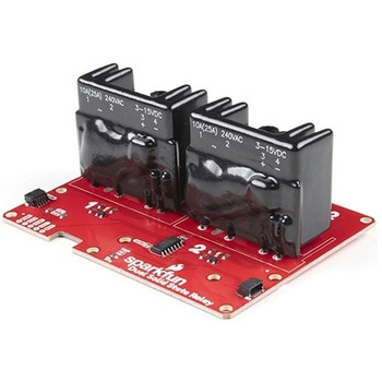
SparkFun Qwiic Dual Solid State Relay
SPARKFUN¥39,980税込¥43,9781個33日以内出荷Description。The SparkFun Qwiic Dual Solid State Relay is a power delivery board that allows users to switch two AC loads from a low power microcontroller using the SparkFun Qwiic connect system. The board features two 25A/250VAC solid state relays that utilize the Zero Cross Trigger method so you can toggle two loads on a 60Hz AC carrier signal on and off up to 120 times per second!。An ATTiny84 acts as the "brain" of the SparkFun Qwiic Dual Solid Relay to accept I2C commands to toggle the two relays as well as a few other special commands. The I2C address of the ATtiny84A is software configurable so, if you have a seriously big power project in mind, you could daisy chain over 100 Qwiic Dual Solid State Relays.。Messing with such high voltage is dangerous! We've included many safety precautions onto the PCB including ground isolation between the relay and other circuitry and a milled out area isolating each side of AC. However, with all the safety precautions included with the SparkFun Qwiic Dual Solid State Relay, this is still a power accessory for users who are experienced around, and knowledgeable about high AC voltage. If you're not comfortable with handling AC voltage in this way, you may want to check out the IoT Power Relay instead.。Note:The relays are rated for a max of 25A with forced air cooling. If you do not have forced air cooling, 10A max through the relays is recommended.。The SparkFun Qwiic connect system is an ecosystem of I2C sensors, actuators, shields and cables that make prototyping faster and less prone to error. All Qwiic-enabled boards use a common 1mm pitch, 4-pin JST connector. This reduces the amount of required PCB space, and polarized connections mean you can't hook it up wrong.。Get Started with the SparkFun Qwiic Dual Solid State Relay Guide。Features。Operating Voltage:2.5-3.6V(3.3V recommended)。I2C Address:0x0A(Default)0x0B(Alternate via jumper select)。Load Voltage Range:12-280VAC。Max Current(Through Relay):25A(240VAC with forced air cooling)。Zero Cross Trigger。Normally Open Circuit Only。2x Qwiic Connectorアズワン品番67-0421-58

『オフィスサプライ』には他にこんなカテゴリがあります
![Sashiko Tenplate 一目刺し 刺し子テンプレート Cosmo[縫製用品]](https://jp.images-monotaro.com/Monotaro3/pi/middle/mono_image_na.jpg "Sashiko Tenplate 一目刺し 刺し子テンプレート Cosmo[縫製用品]")