カテゴリ
- すべてのカテゴリ
- オフィスサプライ
- 学童・教育用品
- 理科/技術/科学工作(83)
- 学童・教育用品
- オフィスサプライ
絞り込み


LEDドライバ
SPARKFUN¥2,498税込¥2,7481個33日以内出荷Description。This is the FemtoBuck, a small-size single-output constant current LED driver. Each FemtoBuck has the capability to dim a single high-power channel of LEDs from 0-350mA at up to 36V while the dimming control can be either accessed via PWM or analog signal from 0-2.5V. This board is based off of the PicoBuck LED Driver, developed in collaboration with Ethan Zonca, except instead of blending three different LEDs on three different channels the FemtoBuck controls just one.。For the FemtoBuck, we've increased the voltage ratings on the parts to allow the input voltage to cover the full 36V range of the AL8805 driver. Since the FemtoBuck is a constant current driver, the current drawn from the supply will drop as supply voltage rises. In general, efficiency of the FemtoBuck is around 95%, depending on the input voltage. On board each FemtoBuck you will find two inputs for both power input and dimming control pins and an area to install a 3.5mm screw terminal. Finally at either side of the board you will find small indents or "ears" which will allow you to use a zip tie to secure the wires to the board after soldering them down. This version of the FemtoBuck is equipped with a small solder jumper that can be closed with a glob of solder to double the output current from 330mA to 660mA.アズワン品番67-0477-97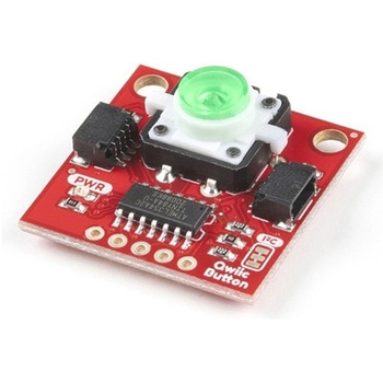
SparkFun Qwiic Button - Green LED
SPARKFUN¥1,698税込¥1,8681個33日以内出荷Description。Buttons are an easy and tactile way to interface with your project, but why would you want to deal with debouncing, polling, and wiring up pull-up resistors? The Qwiic Button with built-in green LED simplifies all of those nasty worries away into an easy to use I2C device! Utilizing our Qwiic Connect System, using the button is as simple as connecting cable and loading up some pre-written code!。If you need multiple buttons for your project, fear not! Each button has configurable I2C address, so you can daisy-chain multiple buttons over Qwiic and still address each one individually. We've got an example in our Arduino library that provides super-easy way to configure your Qwiic Button to whatever I2C address you desire. You can download the library through the Arduino library manager by searching 'SparkFun Qwiic Button' or you can get the GitHub repo as .zip file and install the library from there.。In addition to handling blinking and debouncing, the Qwiic Button has configurable interrupts that can be configured to activate upon button press or click. We've also taken the liberty of implementing FIFO queue onboard the Qwiic Button where it keeps an internal record of when the button was pressed. This means that code on your microcontroller need not waste valuable processing time checking the status of the button but instead can run small function whenever the button is pressed or clicked! For more information on interrupts check out our guide here!。The SparkFun Qwiic Connect System is an ecosystem of I2C sensors, actuators, shields and cables that make prototyping faster and less prone to error. All Qwiic-enabled boards use common 1mm pitch, 4-pin JST connector. This reduces the amount of required PCB space, and polarized connections mean you can't hook it up wrong.。Get Started with the SparkFun Qwiic Button Guide。Features。12mm Green LED Button rated for 50mA。Built in LED can be configured for your desired level of blinkiness!。Each button has configurable I2C address。Configurable interrupts check out our guide here!。FIFO queue。Don't like the color green? Check out the SparkFun Qwiic Button Breakout and add another colored button!。Red LED Tactile Button。Blue LED Tactile Button。Green LED Tactile Button。White LED Tactile Buttonアズワン品番67-0420-14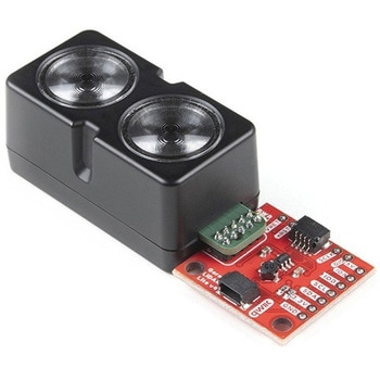
Garmin LIDAR-Lite v4 LED - Distance Measurement Sensor Qwiic
SPARKFUN¥37,980税込¥41,7781個33日以内出荷Description。The LIDAR-Lite v4 Qwiic from GARMIN is a high-performance, wireless optical distance measurement sensor that doesn't require any soldering to get started. This is the ideal solution for drone, robot, IoT, or unmanned vehicle operations whenアズワン品番67-0427-53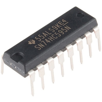
Shift Register 8-Bit - SN74HC595
SPARKFUN¥259税込¥2851個当日出荷Description。The SN74HC595N is a simple 8-bit shift register IC. Simply put, this shift register is a device that allows additional inputs or outputs to be added to a microcontroller by converting data between parallel and serial formats. Your chosen microprocessor is able to communicate with the The SN74HC595N using serial information then gathers or outputs information in a parallel(multi-pin)format. Essentially it takes 8 bits from the serial input and then outputs them to 8 pins.。This small DIP packaged IC contains an 8-bit, serial-in parallel-out shift register that feeds an 8-bit D-type storage register with parallel 3-state outputs.。Note:。This is a drop-in replacement for the 74HC595 shift register IC and should function just fine in any application the previous version could.。Get started with the Shift Register Guide。Features。8-Bit Serial-In, Parallel-Out Shift。Wide Operating Voltage Range of 2 V to 6 V。High-Current 3-State Outputs Can Drive Up to 15 LSTTL Loads。Low Power Consumption:80-μA。±6-mA Output Drive at 5 Vアズワン品番67-0420-82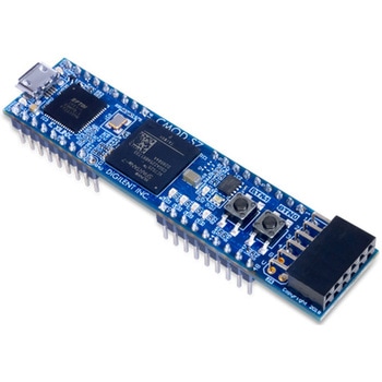
Cmod S7 Spartan-7 FPGA Module
DIGILENT¥27,980税込¥30,7781個12日以内出荷Description。The Cmod, or Carrier Module, family of products is designed to offer quick, simple, and flexible integration of an FPGA into circuit design, prototyping, and learning/hobby projects.The Digilent Cmod S7 is a small, 48-pin DIP form factor board, populated with 36 pins, built around a Xilinx Spartan-7 FPGA that brings FPGA power and prototyping to a solderless breadboard.The board includes a Quad-SPI flash for programming, as well as a USB-JTAG programming circuit and USB-UART bridge. The Cmod S7 also features a clock source, Pmod port, and onboard I/O with LEDs and pushbuttons. There are 32 FPGA I/O signals, 2 FPGA analog input signals, an external power input rail, and ground that are routed to 100-mil-spaced through-hole pins, making the Cmod S7 compatible with solderless breadboards. This form factor makes the Cmod S7 a great option for flexible and affordable prototyping, or learning FPGA and digital logic circuits. At just .7 by 3.05, it can also be loaded in a standard socket and used in embedded systems.The Spartan-7 FPGA on the Cmod S7 fits performance into a small form-factor packaging. With the MicroBlaze Soft Processor Core from Xilinx, you can create embedded applications with a variety of peripherals, memory, and interfaces.If your design requires transceiver lines or more FPGA resources, we recommend the higher-performance Cmod A7, featuring an Artix-7 FPGA.Guides and demos are available to help users get started quickly with the Cmod S7. These can be found through the Support Materials tab.。Features。Xilinx Spartan-7 FPGA(XC7S25-1CSGA225C)。〇3,650 slices containing four 6-input LUTs and 8 flip-flops。〇1,620 Kbits of fast block RAM。〇Three clock management tile, each with a phase-locked loop and mixed-mode clock manager。〇80 DSP slices。〇Internal clock speeds exceeding 450 MHz。〇On-chip analog-to-digital converter(XADC)。〇Programmable over JTAG and Quad-SPI Flash。Memory。〇4 MBQuad-SPI Flash。Power。〇Powered from USB or 5V external supply connected to DIP pin 24(micro USB cable NOT included)。USB。〇USB-JTAG programming circuitry。〇USB-UART bridge。Push-buttons and LEDs。〇2 Buttons。〇4 LEDs。〇1 RGB LED。Expansion Connectors。〇1 Pmod connector。8 total FPGA I/O。〇48-pin DIP form-factor headers。36 populated pins。■32 total FPGA I/O。■2 Single-ended 0-3.3V analog inputs to XADC。Product Compliance:。〇HTC:8473301180。〇ECCN:EAR99。What's Included。Cmod S7 Module。Custom Digilent cardboard box with protective foamアズワン品番67-0390-84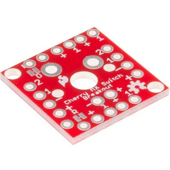
Cherry MX Switch Breakout
SPARKFUN¥799税込¥8791個33日以内出荷Description。Cherry MX Keyswitches are top-of-the-line mechanical keyboard switches. They're satisfyingly "clicky", reliable up to tens-of-millions of key presses, and a standard in gaming and programming keyboards across the globe. With the SparkFun Cherry MX Switch Breakout we have made the switches more easily adaptable to breadboard or perfboard-based projects. The Cherry MX Switch Breakout is a perfect prototyping tool for projects ranging from a single-key user-input to fully-custom 101-key keyboards.。In addition to breaking out the switch contacts to breadboard-compatible headers, the Cherry MX Switch Breakout also provides access to an optional switch-mounted LED. Plus, the pin break-outs are designed with keyboard matrix-ing in mind, so you can interconnect as many boards as you'd like into a row-column configuration, keeping the I/O-pin requirements as low as possible.。Note:If you are looking for a Cherry MX Switch to use with this breakout, we've got you covered! CLICK HERE!。Get Started with the Cherry MX Switch Guide。Features。Support for 3mm LED。Footprint for LED current-limiting resistor。Footprint for switch-isolating diode。Chain-able in row/column matrices。Designed to match standard key spacing and keyboard row offsetsアズワン品番67-0419-91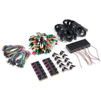
SparkFun Educator Lab Pack for micro:bit v2
SPARKFUN¥109,800税込¥120,7801個33日以内出荷Description。The micro:bit v2 Educator's Lab Pack includes 10 micro:bit v2 boards and everything you need to get you started with the new learning platform. The Lab Pack has everything you need, including micro:bits, cables, battery packs and a few parts to experiment with. This package provides an easy way to introduce your students to the micro:bit without any difficulty or parts hunting.。SparkFun packages everything educators need to get started with the micro:bit in a variety of classroom settings and learning environments. The hardware boards, cables and extra parts come pre-packaged. Examples and curriculum materials are available from SparkFun and micro:bit, as well as from other educators involved in this growing maker education movement.。Lab Packs are your classroom entry point. By combining our kits, popular boards and other educational tools with support materials(to be updated), SparkFun brings all the power of the open source community to the classroom. We've also updated the battery pack to be closer to what is in other micro:bit kits. It now requires 2xAAA batteries.。The micro:bit is a pocket-sized computer that lets you get creative with digital technology. Between the micro:bit and our shield-like bit boards you can do almost anything while coding, customizing and controlling your micro:bit from almost anywhere! You can use your micro:bit for all sorts of unique creations, from robots to musical instruments and more. At half the size of a credit card, this versatile board has vast potential!。。Features。Micro:bit 2.0:64 MHz Arm Cortex-M4 with FPU。512KB Flash。128KB RAM。5x5 Red LED Array。Two Programmable Buttons, one touch sensitive logo。MEMS microphone and LED indicator。Onboard Light, Compass, Accelerometer, Temp Sensors and Speaker。2.4 Ghz Micro:bit Radio/BLE 5.0 Smart Antenna。25-pin Edge Connector。4 dedicated GPIO, PWM, i2c, SPI, and ext. power。Three Digital/Analog Input/Output Rings。Two Power Rings --- 3V and GND。Dedcated I2C bus for peripherals。MicroUSB Connector(5V)。JST-PH Battery Connector(。Not。JST-XH)(3V)。Power/reset Button with Status LED。200 mA available for accessories。Program with C++, MakeCode, Python, Scratchアズワン品番67-0424-92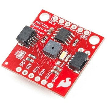
SparkFun Spectral Sensor Breakout - AS7263 NIR Qwiic
SPARKFUN¥9,998税込¥10,9981個33日以内出荷Description。The SparkFun AS7263 Near Infrared(NIR)Spectral Sensor Breakout brings spectroscopy to the palm of your hand, making it easier than ever to measure and characterize how different materials absorb and reflect different wavelengths of light. The AS7263 Breakout is unique in its ability to communicate by both an I2C interface and serial interface using AT commands. Hookup is easy, thanks to the Qwiic connectors attached to the board --- simply plug one end of the Qwiic cable into the breakout and the other into one of the Qwiic shields, then stack the board on a development board. You'll be ready to upload a sketch to start taking spectroscopy measurements in no time.。The AS7263 spectrometer detects wavelengths in the visible range at 610, 680, 730, 760, 810 and 860nm of light, each with 20nm of full-width half-max detection. The board also has multiple ways for you to illuminate objects that you will try to measure for a more accurate spectroscopy reading. There is an onboard LED that has been picked out specifically for this task, as well as two pins to solder your own LED into.。Note:The I2C address of the AS7263 is 0x49 and is hardware defined. A multiplexer/Mux is required to communicate to multiple AS7263 sensors on a single bus. If you need to use more than one AS7263 sensor consider using the Qwiic Mux Breakout.。The SparkFun Qwiic Connect System is an ecosystem of I2C sensors, actuators, shields and cables that make prototyping faster and less prone to error. All Qwiic-enabled boards use a common 1mm pitch, 4-pin JST connector. This reduces the amount of required PCB space, and polarized connections mean you can't hook it up wrong.。Get Started with the SparkFun AS726X Spectral Sensor Breakout Guide。Features。6 near-IR channels:610nm, 680nm, 730nm, 760nm, 810nm and 860nm, each with 20nm FWHM。NIR filter set realized by silicon interference filters。16-bit ADC with digital access。Programmable LED drivers。2.7V to 3.6V with I2C interface。2x Qwiic connectorsアズワン品番67-0426-70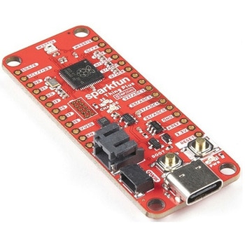
SparkFun Thing Plus - RP2040
SPARKFUN¥6,698税込¥7,3681個33日以内出荷Description。The SparkFun Thing Plus - RP2040 is a low-cost, high performance board with flexible digital interfaces featuring the Raspberry Pi Foundation's RP2040 microcontroller. Besides the Thing Plus or。Feather。footprint(with 18 GPIO pins), the board also includes an SD card slot, 16MB(128Mbit)flash memory, a JST single cell battery connector(with a charging circuit and fuel gauge sensor), an addressable WS2812 RGB LED, JTAG PTH pins, four(4-40 screw)mounting holes, and our signature Qwiic connector.。The RP2040 contains two ARM Cortex-M0+ processors(up to 133MHz)and features:264kB of embedded SRAM in six banks。6 dedicated IO for SPI Flash(supporting XIP)。30 multifunction GPIO:Dedicated hardware for commonly used peripherals。Programmable IO for extended peripheral support。Four 12-bit ADC channels with internal temperature sensor(up to 0.5 MSa/s)。USB 1.1 Host/Device functionality。The RP2040 is supported with both C/C++ and MicroPython cross-platform development environments, including easy access to runtime debugging. It has UF2 boot and floating-point routines baked into the chip. While the chip has a large amount of internal RAM, the board includes an additional 16MB of external QSPI flash memory to store program code.。The SparkFun Qwiic Connect System is an ecosystem of I2C sensors, actuators, shields and cables that make prototyping faster and less prone to error. All Qwiic-enabled boards use a common 1mm pitch, 4-pin JST connector. This reduces the amount of required PCB space, and polarized connections mean you can't hook it up wrong.。Get Started With the Thing Plus RP2040 Hookup Guide。Features。SparkFun Thing Plus - RP2040 Features。Raspberry Pi Foundation's RP2040 microcontroller。16MB QSPI Flash Memory。JTAG PTH Pins。Thing Plus(or Feather)Form-Factor:18[1]x Multifunctional GPIO Pins[2]。Four available 12-bit ADC channels with internal temperature sensor(500kSa/s)。Up to eight 2-channel PWM。Up to two UARTs。Up to two I2C buses。Up to two SPI buses。USB-C Connector:USB 1.1 Host/Device functionality。2-pin JST Connector for a LiPo Battery。(not included)。500mA charging circuit。Qwiic Connector。Buttons:Boot。Reset。LEDs:PWR。- Red 3.3V power indicator。CHG。- Yellow battery charging indicator。25。- Blue status/test LED(。GPIO 25。)。WS2812。- Addressable RGB LED(。GPIO 08。)。Four Mounting Holes:4-40 screw compatible。Dimensions:2.3"×0.9"。RP2040 General Features。Dual Cortex M0+ processors, up to 133 MHz。264 kB of embedded SRAM in 6 banks。6 dedicated IO for QSPI flash, supporting execute in place(XIP)。30 programmable IO for extended peripheral support。SWD interface。Timer with 4 alarms。Real time counter(RTC)。USB 1.1 Host/Device functionality。Supported programming languages。MicroPython。C/C++。1.。Note:。GPIO 08。is not included in this count, as it passes through the WS2812 addressable RGB LED first.。GPIO 07。and。GPIO 23。are counted as a single GPIO because they are tied together.。2.。Note:The GPIO pins are programmable so you can reconfigure the pins! Check out the RP2040 datasheet for more information on the GPIO functionality.アズワン品番67-0423-56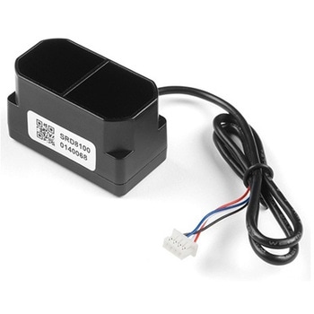
TFMini Plus - Micro LiDAR Module
SPARKFUN¥28,980税込¥31,8781個33日以内出荷Description。The TFMini Plus is a ToF(Time of Flight)LiDAR sensor capable of measuring the distance to an object as close as 10 centimeters(+/- 5cm up to 6m)and as far as 12 meters(+/-1% starting at 6m)! As with all LiDAR sensors, your effective detection distance will vary depending on lighting conditions and the reflectivity of your target object, but what makes this sensor special is its size. Measuring only 35x18.5x21mm, the TFMini Plus allows you to integrate LiDAR into applications traditionally reserved for smaller sensors.。Setting itself apart from the original TFmini, the TFmini Plus has been designed with an IP65 enclosure meaning its "Dust tight water resistant", and also passed the vibration test of drone level, which will greatly expand its application range. The TFMini Plus is easy to power at only 5V and easy to talk to using the UART communication protocol.。Important:This product does not use laser light for ranging. Instead it contains an LED and optics. Many such systems are being marketed under the name "LiDAR," although it may be more appropriate to think of this device as a "Time-of-Flight Infrared Rangefinder". It differs significantly from traditional IR rangefinders in that it uses ToF to determine range and not triangulation ― as is performed by the Sharp GP-series devices.。Features。Operating Range - 0.1m~12m1。Accuracy - ±5cm@(0.1-6m), ±1%@(6m-12m)。Distance resolution - 5mm。Frame rate - 1-1000Hz(adjustable)。Ambient light immunity - 70klux。Operating temperature - -20℃~60℃。Enclosure rating - IP65。Light source - LED。Central wavelength - 850nm。FOV - 3.6°。Supply voltage - 5V±0.5V。Average current - ≦110mA。Power consumption - 550mW。Peak current - 500mA。Communication level - LVTTL(3.3V)。Material of enclosure - ABS+PC。Storage temperature - -20℃~75℃。Weight - 11g。Wire length - 30cmアズワン品番67-0426-94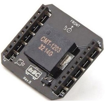
Crazyflie 2.0 - Buzzer deck
Seeed Studio¥2,398税込¥2,6381個33日以内出荷Sometimes LED feedback isn't enough、like when you're flying around in a lab or a living room. With the buzzer deck you'll get audio feedback on system events、like low battery or charging completed. Or why not create your own melodies that will play while you're buzzing around. To get started using the buzzer deck there's already a few melodies pre-programmed in the Crazyflie 2.0 latest firmware.。This product is intended to be used together with the Crazyflie 2.0 nano quadcopter and uses its expansion board system. Please have a look at the buyers guide for more info about the Crazyflie 2.0 ecosystem. For more information about how to use the expansion decks check out the getting started with expansion decks page.。Features:Low profile piezo buzzer for tone and melody generation。Automatic detection of deck。Specifications。Based on the CMT-1203-SMT。1-wire memory for automatic deck detection。Mechanical specification。Weight:1.8g。Size(WxHxD):25x27x4mm。Designed for mounting above or under the Crazyflie 2.0。Part list。1×Buzzer deck仕様●項目1:組込み(完成機能)●項目2:オーディオ、サウンド●項目4:ブザー、サウンダー●項目8:Crazyflie用アズワン品番67-0461-81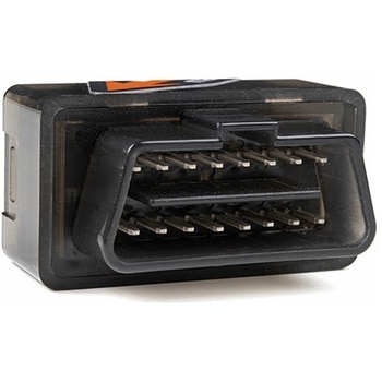
Macchina A0 OBD-II Development Module
SPARKFUN¥30,980税込¥34,0781個33日以内出荷Description。The A0 in the latest in Macchina's line of OBD-II interfaces. The A0 uses the power of the ESP32 BLE and WiFi module to allow for wireless access to the OBD-II port most modern cars have.。The Macchina A0 module plugs directly into the OBD-II port found in most modern cars and receives its power from the port. From there, one can interface with the device through a few different methods. The easiest is with software such as SavvyCAN, Torque Lite on Android. Besides getting all on board diagnostic information, you're able to control certain aspects of the car and create cool projects such as dash-mounted, shift lights. The A0 can also be programmed in the Arduino IDE, so there's plenty of possibilities to customize the device for what you want to do with your car!。Features。ODB-II compatibility with all modern cars(1996 or newer)。Pre-loaded with SavvyCAN for plug and play(wireless!)reverse engineering。WiFi and Bluetooth(R)Functionality。ESP32 Processor。Super bright RGB LED。CAN Communication Functionality。Programmable with the Arduino IDEアズワン品番67-0423-39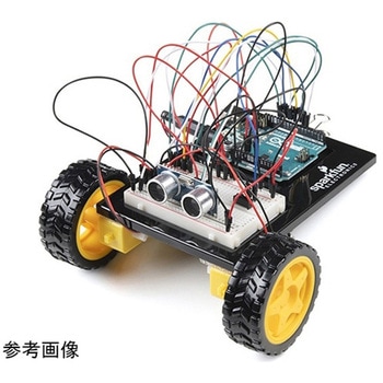
SparkFun Inventor's Kit for Arduino Uno - v4.1
SPARKFUN¥34,980税込¥38,4781個33日以内出荷。Description。The SparkFun Inventor's Kit(SIK)for Arduino Uno is a great way to get started with programming and hardware interaction with the Arduino programming language. The SIK includes everything you need to complete five overarching projects consisting of 16 interconnected circuits that teach everything from blinking an LED to reading sensors. The culminating project is your very own autonomous robot! No previous programming or electronics experience is required to use this kit.。The online guide contains step-by-step instructions with circuit diagrams and hookup tables for building each project and circuit with the included parts. Full example code is provided, new concepts and components are explained at point of use, and troubleshooting tips offer assistance if something goes wrong.。The kit does not require any soldering and is recommended for beginners ages 10 and up who are looking for an Arduino starter kit. For SIK version 4.1 we took an entirely different approach to teaching embedded electronics. In previous versions of the SIK, each circuit focused on introducing a new piece of technology. With SIK v4.1, components are introduced in the context of the circuit you are building, and each circuit builds upon the last, leading up to a project that incorporates all of the components and concepts introduced throughout the guide. With new parts and a completely new strategy, even if you've used the SIK before, you're in for a brand-new experience!。This version of the SIK replaces the SparkFun RedBoard Qwiic with the Arduino Uno(SMD version)and comes without the SIK guidebook and carrying case. With these components being swapped and removed, we were able to reduce the overall size and weight of the kit, making shipping cheaper and easier for anyone ordering internationally.。Note:As stated above, this SIK does NOT include a carrying case or print guidebook.。Get Started With the SparkFun Inventor's Kit v4.1 Experiment Guide。Examples。Project 1:Light。Circuit 1A:Blinking an LED。Circuit 1B:Potentiometer。Circuit 1C:Photoresistor。Circuit 1D:RGB Night-Light。Project 2:Sound。Circuit 2A:Buzzer。Circuit 2B:Digital Trumpet。Circuit 2C:"Simon Says" Game。Project 3:Motion。Circuit 3A:Servo Motors。Circuit 3B:Distance Sensor。Circuit 3C:Motion Alarm。Project 4:Display。Circuit 4A:LCD "Hello, World!"。Circuit 4B:Temperature Sensor。Circuit 4C:"DIY Who Am I?" Game。Project 5:Robot。Circuit 5A:Motor Basics。Circuit 5B:Remote-Controlled Robot。Circuit 5C:Autonomous Robotアズワン品番67-0424-34
SparkFun Qwiic Alphanumeric Display - COMシリーズ
SPARKFUN¥2,998税込¥3,2981個33日以内出荷Description。The SparkFun Alphanumeric Display Arduino library makes printing strings to the display as easy as calling the print()function. With this library, you'll be able to send I2C commands to the VK16K33 LED driver chip to light up segments(including the decimal point or colon)and even scroll your string across the display. You can download the library through the Arduino library manager by searching 'SparkFun Alphanumeric Display' or you can get the GitHub repo as a .zip file and install the library from there.。The SparkFun Qwiic Connect System is an ecosystem of I2C sensors, actuators, shields and cables that make prototyping faster and less prone to error. All Qwiic-enabled boards use a common 1mm pitch, 4-pin JST connector. This reduces the amount of required PCB space, and polarized connections mean you can't hook it up wrong.。Get Started with the Qwiic Alphanumeric Display Hookup Guide。Features。Operating Voltage:3.3V。Integrated RC oscillator。Maximum display segment numbers:128 patterns。13×3 matrix key scan circuit。16-step dimming circuit。I2C Addresses:0x70(0x71, 0x72, 0x73)。2x Qwiic connectors。2x Wall Mounting Pointsアズワン品番67-0421-61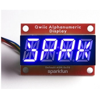
SparkFun Qwiic Alphanumeric Display - COMシリーズ
SPARKFUN¥2,998税込¥3,2981個33日以内出荷Description。The SparkFun Alphanumeric Display Arduino library makes printing strings to the display as easy as calling the print()function. With this library, you'll be able to send I2C commands to the VK16K33 LED driver chip to light up segments(including the decimal point or colon)and even scroll your string across the display. You can download the library through the Arduino library manager by searching 'SparkFun Alphanumeric Display' or you can get the GitHub repo as a .zip file and install the library from there.。The SparkFun Qwiic Connect System is an ecosystem of I2C sensors, actuators, shields and cables that make prototyping faster and less prone to error. All Qwiic-enabled boards use a common 1mm pitch, 4-pin JST connector. This reduces the amount of required PCB space, and polarized connections mean you can't hook it up wrong.。Get Started with the Qwiic Alphanumeric Display Hookup Guide。Features。Operating Voltage:3.3V。Integrated RC oscillator。Maximum display segment numbers:128 patterns。13×3 matrix key scan circuit。16-step dimming circuit。I2C Addresses:0x70(0x71, 0x72, 0x73)。2x Qwiic connectors。2x Wall Mounting Pointsアズワン品番67-0421-62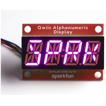
SparkFun Qwiic Alphanumeric Display - COMシリーズ
SPARKFUN¥3,198税込¥3,5181個33日以内出荷Description。The SparkFun Alphanumeric Display Arduino library makes printing strings to the display as easy as calling the print()function. With this library, you'll be able to send I2C commands to the VK16K33 LED driver chip to light up segments(including the decimal point or colon)and even scroll your string across the display. You can download the library through the Arduino library manager by searching 'SparkFun Alphanumeric Display' or you can get the GitHub repo as a .zip file and install the library from there.。The SparkFun Qwiic Connect System is an ecosystem of I2C sensors, actuators, shields and cables that make prototyping faster and less prone to error. All Qwiic-enabled boards use a common 1mm pitch, 4-pin JST connector. This reduces the amount of required PCB space, and polarized connections mean you can't hook it up wrong.。Get Started with the Qwiic Alphanumeric Display Hookup Guide。Features。Operating Voltage:3.3V。Integrated RC oscillator。Maximum display segment numbers:128 patterns。13×3 matrix key scan circuit。16-step dimming circuit。I2C Addresses:0x70(0x71, 0x72, 0x73)。2x Qwiic connectors。2x Wall Mounting Pointsアズワン品番67-0421-64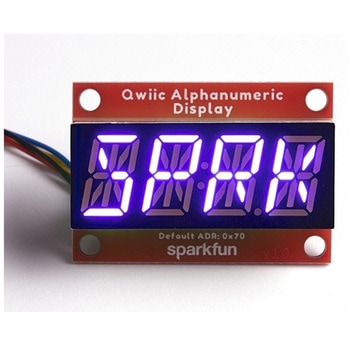
SparkFun Qwiic Alphanumeric Display - COMシリーズ
SPARKFUN¥2,998税込¥3,2981個33日以内出荷Description。The SparkFun Alphanumeric Display Arduino library makes printing strings to the display as easy as calling the print()function. With this library, you'll be able to send I2C commands to the VK16K33 LED driver chip to light up segments(including the decimal point or colon)and even scroll your string across the display. You can download the library through the Arduino library manager by searching 'SparkFun Alphanumeric Display' or you can get the GitHub repo as a .zip file and install the library from there.。The SparkFun Qwiic Connect System is an ecosystem of I2C sensors, actuators, shields and cables that make prototyping faster and less prone to error. All Qwiic-enabled boards use a common 1mm pitch, 4-pin JST connector. This reduces the amount of required PCB space, and polarized connections mean you can't hook it up wrong.。Get Started with the Qwiic Alphanumeric Display Hookup Guide。Features。Operating Voltage:3.3V。Integrated RC oscillator。Maximum display segment numbers:128 patterns。13×3 matrix key scan circuit。16-step dimming circuit。I2C Addresses:0x70(0x71, 0x72, 0x73)。2x Qwiic connectors。2x Wall Mounting Pointsアズワン品番67-0421-63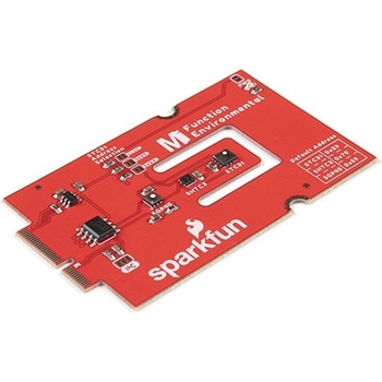
SparkFun MicroMod Environmental Function Board
SPARKFUN¥44,980税込¥49,4781個33日以内出荷Description。The SparkFun MicroMod Environmental Function Board adds additional sensing options to the MicroMod Processor Boards. This Function Board includes three sensors to monitor air quality(SGP40), humidity temperature(SHTC3), and CO2 concentrations(STC31)in your indoor environment. To make it even easier to use, all communication is over the MicroMod's I2C bus!。The SGP40 measures the quality of the air in your room or house. The SGP40 uses a metal oxide(MOx)sensor with a temperature controlled micro hotplate and provides a humidity-compensated volatile organic compound(VOC)based indoor air quality signal. Both the sensing element and VOC Algorithm feature an unmatched robustness against contaminating gases present in real world applications enabling a unique long term stability as well as low drift and device to device variation.。The SHTC3 is a highly accurate digital humidity and temperature sensor. The SHTC3 uses a capacitive humidity sensor with a relative humidity measurement range of 0 to 100% RH and bandgap temperature sensor with a temperature measurement range of -40℃ to 125℃. The SHTC3 builds on the success of their SHTC1 sensor with higher accuracy(±2% RH, ±0.2℃)than its predecessor, enabling greater flexibility.。The STC31 measures CO2 concentrations based on thermal conductivity and has two CO2 measurement ranges:0 to 25 vol%; and 0 to 100 vol%. The measurement repeatability is 0.2 vol%, with a stability of 0.025 vol% / ℃. The measurement accuracy depends on the measurement range:0.5 vol% + 3% measured value; 1 vol% + 3% measured value. Using measurements from the SHTC3, the STC31 is able to provide humidity-compensated measurements together with improved temperature compensation. The STC31 can compensate for atmospheric pressure too - which is handy if, like us, you're up in the mountains!。The outstanding performance of these three sensors is based on Sensirion's patented CMOSens(R)technology, which combines the sensor element, signal processing, and digital calibration on a small CMOS chip. The well-proven CMOS technology is perfectly suited for high-quality mass production and is the ideal choice for demanding and cost-sensitive OEM applications.。Utilizing our handy M.2 MicroMod connector, no soldering is required to connect it to your system. Simply match up the key on your processor and function board's beveled edge connector to their respective key on the M.2 connector, then secure them to the main board with screws. The MicroMod Environmental Function Board can then be read via the I2C port. The board is equipped with the AP2112 3.3V voltage regulator, I2C pull-up resistors, power LED, jumper to disable the LED, and jumpers for alternative STC31 addresses.。Note:A MicroMod Processor and Main Board are not included with this MicroMod Environmental Function Board. These boards will need to be purchased separately.。MicroMod is a modular interface ecosystem that connects a microcontroller "processor board" to various "carrier board" peripherals. Utilizing the M.2 standard, the MicroMod standard is designed to easily swap out processors and function boards on the fly. Pair a specialized carrier board for the project you need with your choice of compatible processor!。Get Started with the MicroMod Environmental Function Board。Features。Input voltage range。2.5V to 6.0V。Typ.。5V。via Main Board's USB connector。Typ.。~3.7V to 4.2V。via Main Board's LiPo battery Connector。I/O voltage。3.3V。AP2112 3.3V voltage regulator(rated 600mA)。Power LED。I2C pull-up resistors。Sensirion SGP40 Air Quality Sensor。Uses I2C interface。Address:0x59(default)。Operating voltage range。1.7V to 3.6V(Typ.。3.3V。)。Operating temperature range。-20℃ to +55℃。Typical current consumption。2.6mA。during continuous operation(at 3.3V)。34μA。when idle(heater off)。Output signal。Digital raw value(SRAW):0 - 65535 ticks。Digital processed value(VOC Index):0 - 500 VOC index points。Switch-on behavior。Time until reliably detecting VOC events:<60s。Time until specifications are met:<1h。Recommended sampling interval。VOC Index:1s。SRAW:0.5s - 10s(Typ. 1s)。Sensirion SHTC3 Humidity and Temperature Sensor。Uses I2C interface。Address:0x70(default, non-configurable)。Operating voltage range。1.62V - 3.6V(Typ.。3.3V。)。Operating temperature range。-40℃ to +125 ℃。Relative Humidity。Measurement range:0% to 100%。Typical accuracy:±2 %RH。Resolution:0.01 %RH。Temperature。Measurement range:-40℃ to +125 ℃。Typical accuracy:±0.2 ℃。Resolution:0.01 ℃。Typical current consumption(varies based on mode)。4.9μA to 430μA(Normal Mode)。0.5μA to 270μA(Low Power Mode)。Allows the STC31 to compensate for humidity and temperature。Sensirion STC31 CO2 Sensor。Uses I2C interface。Addresses:0x29(default)。, 0x2A, 0x2B, 0x2C。Operating voltage range。2.7V to 5.5V(Typ.。3.3V。)。Operating temperature range。-20 ℃ to +85 ℃。Calibrated for CO2 in N2 and CO2 in air。Measurement ranges。0 to 25 vol% in N2。0 to 100 vol% in air。Accuracy。0.5 vol% + 3% measured value in N2。1 vol% + 3% measured value in air。Concentration and temperature resolution:16-bit。Repeatability:0.2 vol%。Temperature stability:0.025 vol% / ℃。Start-up time:14 ms。Thermal conductivity sensor provides calibrated gas concentration and temperature output。Jumpers。PWR LED。I2C pull-up resistors。STC31 address selection。Note:The I2C addresses that are reserved for each sensor is 0x59(SGP40), 0x70(SHTC3), 0x29(STC31). A multiplexer/Mux is required to communicate to multiple SHTC3 sensors on a single bus. The SHTC3 uses the same address as the Qwiic Mux(0x70). For advanced users that are using multiple SHTC3's with the Qwiic Mux, you will need to adjust the Qwiic Mux's default address.アズワン品番67-0427-60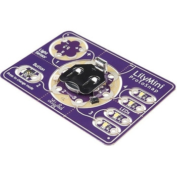
LilyPad LilyMini ProtoSnap
SPARKFUN¥5,998税込¥6,5981個33日以内出荷Description。The LilyMini ProtoSnap is a great way to get started learning about creating interactive e-textile circuits before you start sewing. Like other LilyPad ProtoSnap boards, the LilyMini ProtoSnap has all of its pieces wired together out of the box, enabling you to test the circuit's function before you sew. At the center of the board is a pre-programmed LilyMini microcontroller connected to a LilyPad Light Sensor, LilyPad Button and two pairs of LilyPad LEDs.。The LilyMini ProtoSnap ships with pre-loaded code that uses all the LilyPad pieces connected to it. This sample code has three modes, which can be selected by pressing the LilyPad Button on the bottom-left side of the ProtoSnap. The built-in RGB LED on the LilyMini will change color to indicate which mode has been selected:。White:。All LEDs on.。Magenta:。LEDs fade in and out in a breathing pattern. When the light sensor is covered, LEDs fade faster.。Cyan:。LEDs off. When the light sensor is covered, LEDs will twinkle.。The LilyMini board, at the center of the ProtoSnap, has a built-in battery holder for a CR2032 battery(included). On the opposite side of the LilyMini you will find the SAMD11 brain, which controls the ProtoSnap.。Note:。A portion of this sale is given back to Dr. Leah Buechley for continued development and education in e-textiles.。Note:。The LilyPad LilyMini ProtoSnap does NOT include sewing needles or conductive thread. These items will need to purchased separately.。Warning:You cannot reprogram this product and any attempt at programming is at your own risk!。Get Started with the LilyMini ProtoSnap Guideアズワン品番67-0422-40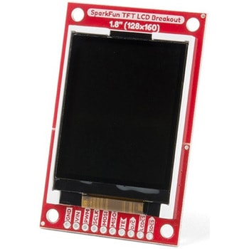
SparkFun TFT LCD Breakout - 1.8" 128x160
SPARKFUN¥9,998税込¥10,9981個33日以内出荷Description。The SparkFun TFT LCD Breakout is a versatile, colorful, and easy way to experiment with graphics or create a user interface for your project. With a 4-wire SPI interface and microSD card holder, you can use this breakout to easily add visual display/interface capabilities to a project as well as providing all the storage you might need for multimedia files.。To get started with this breakout, you will need an Arduino compatible microcontroller of your choice - we recommend something with extra RAM like the SparkFun Thing Plus. The breakout can be powered with either 5V or 3.3V. The microSD card holder is connected to the same SPI bus as the display which keeps the required pin count low and exists to relieve the burden from your microcontroller's poor memory due to having to store hundreds of images of cats, or really whatever you want to keep there. We have also gone ahead and tricked out the SparkFun HyperDisplay library with a driver made especially for this breakout!。Out of the box, the SparkFun TFT LCD Breakout will come with a large backing PCB that makes it easy to securely mount the display in a project. If you need a more flexible solution you can remove the display module, snap off half the backing board, and then re-insert the display module. When this is done you'll be left with the bare minimum frame around the display to more seamLessly integrate with your project.。Get Started With the SparkFun TFT LCD Breakout Guide。Features。128×160 RGB pixels。Up to 18 bit configurable color depth。2x PWM controllabele LED backlight。microSD Card Slot。V-Score for Minimal Footprint Setupアズワン品番67-0424-97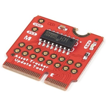
SparkFun MicroMod Update Tool
SPARKFUN¥1,798税込¥1,9781個33日以内出荷。Description。The SparkFun MicroMod Update Tool is built to interface with the MicroMod Asset Tracker Carrier Board and also makes it simple to communicate directly with the u-blox SARA-R510M8S module using u-blox's sophisticated m-center cellular evaluation software. If you're familiar with u-center, u-blox's GNSS evaluation software, you'll know how excellent their software is. m-center is every bit as good. Attach a USB-C cable and away you go!。The Update Tool is not a full MicroMod Processor Board, it is much simpler than that. It has a CH340C USB-Serial converter on it which gives you full access to all eight pins of the SARA-R5's UART interface via the Asset Tracker's USB-C connector. Think of it as a bridge from USB to serial.。The Update Tool features eight pairs of Plated Through Hole connections for the UART signals. You can use these to connect directly to the SARA UART using 3.3V signals if you want to. The split pads on the rear of the Tool can be opened to isolate the CH340C completely; the pins nearest the M.2 will link straight to the SARA UART.。Get Started with the MicroMod Update Tool Hookup Guide。Features。CH340C USB-Serial converter。Eight pairs of Plated Through Hole connections with split pad jumper links for:Serial Transmit(TX)。Serial Receive(RX)。Request To Send(RTS)。Clear To Send(CTS)。Data Terminal Ready(DTR)。Data Set Ready(DSR)。Ring Indicator(RI)。Data Carrier Detect(DCD)。LED indicator for:Power(3.3V)アズワン品番67-0423-52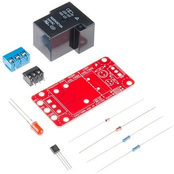
SparkFun Beefcake Relay Control Kit Ver. 2.0
SPARKFUN¥3,198税込¥3,5181個33日以内出荷Description。Your 5V system can wield great power with this big, beefy relay board. How does 10A on the NC contacts and 20A on the NO contacts at 220VAC sound? The SparkFun Beefcake Relay Control Kit contains all the parts you need to get your high-power load under control. Only minimal assembly is required!。The heart of the board is sealed, SPDT 20A/10A Relay. The relay is controlled by 5V logic through transistor, and an LED tells you when the relay is closed. This is kit, so it comes as through-hole parts with assembly required, which makes for some nice soldering practice. Screw terminal connectors on either side of the board make it easy to incorporate into your project.。There are some pretty beefy traces connecting the relay to the load pins, but the 3-pin terminals are only rated for 15A max! If you plan on connecting larger load, you'll need to solder directly to the board. As always with high current and voltage, play it safe and use your judgment when deciding how much of load you want to put on board -- in open airflow the PCB can handle the full 20A for few minutes at time, but in an enclosed area heat can build up.。Note:Please keep in mind that this board is really meant for someone with experience and good knowledge of electricity. If you're uncomfortable soldering or dealing with high voltage, please check out the IoT Power Relay. The IoT Power Relay is fully enclosed, making it lot safer.。Get Started With the Beefcake Hookup Assembly Guide。Features。Voltage Rating:220VAC/28VDC。VCC requirements:4-6V, 150mA capable。SPDT pins exposed(Form C)。14 AWG screw terminals for relay connections.。10 AWG solder lugs for relay connections.。Flyback diode included。Zener recovery diode included(decreases turn-off time)。Heavy oz. copper on PCBアズワン品番67-0424-03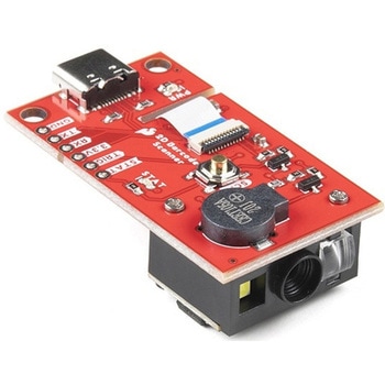
SparkFun 2D Barcode Scanner Breakout
SPARKFUN¥20,980税込¥23,0781個33日以内出荷。Description。The SparkFun 2D Barcode Scanner Breakout is a nifty little breakout board featuring the DE2120 barcode scanner module from DYScan. The DE2120 reads 20 different barcode symbologies(both 1D and 2D)using a camera coupled with on-board image processing to identify and decode everything from UPC codes to QR codes. The module also features two LEDs:one for illumination and one to project the red line that you're used to seeing from laser-based scanners.。This breakout board makes it easy to explore all of the capabilities of the DE2120 without dealing with finicky flat flex cables. The scanner's USB interface is exposed via the on-board USB-C connector. A buzzer and status LED are connected to the module through appropriate drive circuits and a push button tactile switch is provided on the "trigger" pin. When you're ready to incorporate the module into your embedded project, you can leverage the 5 pin header for direct access to the TTL serial pins, power pins, and trigger input.。The module can be configured either by using the serial interface or by scanning command barcodes found in the Settings Manual.。All keyboard, HID, and serial can be transmitted over the single USB-C connector. The DE2120 has the unique ability to enumerate all three protocols including a CDC serial driver so the device appears as a standard COM port.。Get Started with the 2D Barcode Scanner Breakout Hookup Guide。Features。USB-C Connector for USB HID Interface and Virtual COM port。Reads 20 different symbologies。1D Symbologies。UPC-A。UPC-E。EAN-8。EAN-13。Code 128。GS1-128。Code 39。Code 93。Code 11。Interleaved 2-of-5。Matrix 2-of-5。Industrial 2-of-5。Codabar。MSI。GS1 DataBar。Datalogic 2-of-5。2D Symbologies。QR Code。Data Matrix。PDF 417。Micro PDF 417。Aztec Codeアズワン品番67-0430-36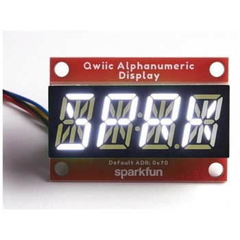
SparkFun Qwiic Alphanumeric Display - White
SPARKFUN¥2,998税込¥3,2981個33日以内出荷Description。We are quite familiar with seven-segment displays. We see them on our alarm clocks, ovens, and microwaves. By adding more segments to each digit you can display more than just numbers! Introducing the brand new SparkFun Qwiic Alphanumeric Display. These white fourteen-segment digits allow you display all sorts of numbers, characters, and symbols. With Qwiic, simply plug it in and go. No soldering, no figuring out which is SDA or SCL, and no voltage regulation or translation required!。The SparkFun Alphanumeric Display Arduino library makes printing strings to the display as easy as calling the print()function. With this library, you'll be able to send I2C commands to the VK16K33 LED driver chip to light up segments(including the decimal point or colon)and even scroll your string across the display. You can download the library through the Arduino library manager by searching 'SparkFun Alphanumeric Display' or you can get the GitHub repo as a .zip file and install the library from there.。The VK16K33 also supports I2C address configuration. Simply close a combination of the address jumpers on the back and you can communicate with up to four displays on the same bus. Our slim board design also features detachable stand off holes, vertical Qwiic connectors, and internal mounting holes.。The SparkFun Qwiic Connect System is an ecosystem of I2C sensors, actuators, shields and cables that make prototyping faster and less prone to error. All Qwiic-enabled boards use a common 1mm pitch, 4-pin JST connector. This reduces the amount of required PCB space, and polarized connections mean you can't hook it up wrong.。Get Started with the Qwiic Alphanumeric Display Hookup Guide。Features。White display。Operating Voltage:3.3V。Integrated RC oscillator。Maximum display segment numbers:128 patterns。13×3 matrix key scan circuit。16-step dimming circuit。I2C Addresses:0x70(0x71, 0x72, 0x73)。2x Qwiic connectors。2x Wall Mounting Pointsアズワン品番67-0421-87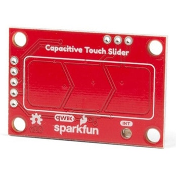
SparkFun Capacitive Touch Slider - CAP1203 Qwiic
SPARKFUN¥2,498税込¥2,7481個33日以内出荷。Description。Do you want to replace a slider or a button on your art project or science experiment with a more interesting interface? This Capacitive Touch Slider is a "Qwiic" and easy way to add capacitive touch to your next project. With the board's built in touch pads, you can immediately start playing with the touch capabilities as three unique touch inputs or as a slider. You can also enable a touch input to act as a power button, customize the sensitivity for your own touch pads, and play with the interrupt alert LED. Utilizing our Qwiic system, no soldering is required to connect it to the rest of your system. However, we have broken out 0.1"-spaced pins in case you prefer to use a breadboard or create your own touch pads.。On the front of the board, there is an arrow shape which contains three separate capacitive touch pads. We also broke out the capacitive touch sensor lines as plated through-holes on the top of the board. You can use these pins to connect to your own capacitive touch pads. The CS1 pin connects to the left pad, the CS2 pin connects to the middle pad, and the CS3 pin connects to the right pad.。NOTE:The I2C address of the CAP1203 is 0x28 and is hardware defined. A multiplexer/Mux is required to communicate to multiple CAP1203 sensors on a single bus. If you need to use more than one CAP1203 sensor consider using the Qwiic Mux Breakout.。The SparkFun Qwiic connect system is an ecosystem of I2C sensors, actuators, shields and cables that make prototyping faster and less prone to error. All Qwiic-enabled boards use a common 1mm pitch, 4-pin JST connector. This reduces the amount of required PCB space, and polarized connections mean you can't hook it up wrong.。Get Started with the SparkFun Capacitive Touch Slider Guide。Features。Capacitive Touch。3 unique capacitive touch inputs。Features。Emulated slider。Power button setting。Programmable sensitivity。Automatic recalibration。I2C Address:0x28。Qwiic Enabled。Operating Range。Supply Voltage:3.3V - 5Vアズワン品番67-0427-06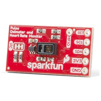
SparkFun Pulse Oximeter and Heart Rate Sensor - MAX30101 & MAX32664 Qwiic
SPARKFUN¥13,980税込¥15,3781個33日以内出荷Description。The SparkFun Pulse Oximeter and Heart Rate Sensor is an I2C based biometric sensor, utilizing two chips from Maxim Integrated:the MAX32664 Biometric Sensor Hub and the MAX30101 Pulse Oximetry and Heart Rate Module. While the latter does all the sensing, the former is an incredibly small and fast Cortex M4 processor that handles all of the algorithmic calculations, digital filtering, pressure/position compensation, advanced R-wave detection, and automatic gain control. We've provided a Qwiic connector to easily connect to the I2C data lines but you will also need to connect to two additional lines. This board is very small, measuring at 1in×0.5in(25.4mm×12.7mm), which means it will fit nicely on your finger without all the bulk.。The MAX30101 does all the sensing by utilizing its internal LEDs to bounce light off the arteries and arterioles in your finger's subcutaneous layer and sensing how much light is absorbed with its photodetectors. This is known as photoplethysmography. This data is passed onto and analyzed by the MAX32664 which applies its algorithms to determine heart rate and blood oxygen saturation(SpO2). SpO2 results are reported as the percentage of hemoglobin that is saturated with oxygen. It also provides useful information such as the sensor's confidence in its reporting as well as a handy finger detection data point. To get the most out of the sensor we've written an Arduino Library to make it easy to adjust all the possible configurations.。The SparkFun Qwiic connect system is an ecosystem of I2C sensors, actuators, shields and cables that make prototyping faster and less prone to error. All Qwiic-enabled boards use a common 1mm pitch, 4-pin JST connector. This reduces the amount of required PCB space, and polarized connections mean you can't hook it up wrong.。Get Started with the Pulse Oximeter and Heart Rate Monitor Hookup Guide。Features。SparkFun Pulse Oximeter and Heart Rate Sensor。MAX30101 and MAX32664 sensor and sensor hub。Qwiic connectors for power and I2C interface。I2C Address:0x55。MAX30101 - Pulse Oximeter and Heart-Rate Sensor。Heart-Rate Monitor and Pulse Oximeter Sensor in LED Reflective Solution。Integrated Cover Glass for Optimal, Robust Performance。Ultra-Low Power Operation for Mobile Devices。Fast Data Output Capability。Robust Motion Artifact Resilience。MAX32664 - Ultra-Low Power Biometric Sensor Hub。Biometric Sensor Hub Solution。Finger-Based Algorithms Measure Pulse Heart Rate and Pulse Blood Oxygenation Saturation(SpO2)。Both Raw and processed data are available。Basic Peripheral mix optimizes size and performanceアズワン品番67-0426-96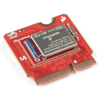
SparkFun MicroMod Artemis Processor
SPARKFUN¥6,198税込¥6,8181個33日以内出荷Description。Leveraging the ultra powerful Artemis Module, the SparkFun MicroMod Artemis Processor is the brain board of your dreams. With a Cortex-M4F with BLE 5.0 running up to 96MHz and with as low power as 6uA per MHz(less than 5mW), the M.2 MicroMod connector allows you to plug in a MicroMod Carrier Board with any number of peripherals. Let's have a look at what this processor board has to offer! If you need Machine Learning capabilities, Bluetooth, I2C functionality to connect to all our amazing Qwiic boards, and more the Artemis Processor is the perfect choice for your MicroMod Carrier Board.。At the heart of SparkFun's Artemis Module is Ambiq Micro's Apollo3 processor, whose ultra-efficient ARM Cortex-M4F processor is spec'd to run TensorFlow Lite using only 6uA/MHz. We've routed two I2C buses, eight GPIO, dedicated digital, analog, and PWM pins, multiple SPI as well as QuadSPI, and Bluetooth to boot. You really can't go wrong with this processor. Grab one today, pick up a compatible carrier board, and get hacking!。MicroMod is a modular interface ecosystem that connects a microcontroller "processor board" to various "carrier board" peripherals. Utilizing the M.2 standard, the MicroMod standard is designed to easily swap out processors on the fly. Pair a specialized carrier board for the project you need with your choice of compatible processor!。Get Started with the MicroMod Artemis Processor Guide。Features。Artemis General Features。1M Flash / 384k RAM。48MHz / 96MHz turbo available。6uA/MHz(operates less than 5mW at full operation)。48 GPIO - all interrupt capable。31 PWM channels。Built in BLE radio and antenna。10 ADC channels with 14-bit precision with up to 2.67 million samples per second effective continuous, multi-slot sampling rate。2 channel differential ADC。2 UARTs。6 I2C buses。6 SPI buses。2/4/8-bit SPI bus。PDM interface。I2S Interface。Secure 'Smart Card' interface。FCC/IC/CE Certified(ID Number 2ASW8-ART3MIS)。Specific Peripherals made available on MicroMod Artemis:1x USB dedicated for programming and debug。1x UART with flow control。2x I2C。1x SPI。1x Quad-SPI。8x Fast GPIO。2x Digital Pins。2x Analog Pins。2x PWM。1x Differential ADC pair。Status LED。VIN Level ADC。Additional peripherals are available but are shared on dedicated MicroMod pins.アズワン品番67-0423-05
SparkFun Qwiic Adapter
SPARKFUN¥479税込¥5271個33日以内出荷Description。The SparkFun Qwiic Adapter provides the perfect means to make any old I2C board into a Qwiic-enabled board. This adapter breaks out the I2C pins from the Qwiic connectors to pins that you can easily solder with your favorite I2C-enabled device.。The Qwiic Adapter has two Qwiic connection ports, all on the same I2C bus. Four plated through holes are broken out for SCL, SDA, 3.3V and GND. These pins can be used to convert an old I2C-enabled device into a Qwiic-enabled board.。The SparkFun Qwiic Connect System is an ecosystem of I2C sensors, actuators, shields and cables that make prototyping faster and less prone to error. All Qwiic-enabled boards use a common 1mm pitch, 4-pin JST connector. This reduces the amount of required PCB space, and polarized connections mean you can't hook it up wrong.。Get Started with the SparkFun Qwiic Adapter Guide。Features。2x Qwiic Connection Ports。Broken-out I2C Pinsアズワン品番67-0419-69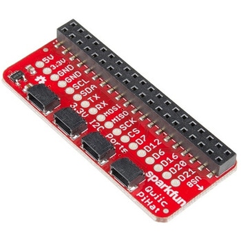
SparkFun Qwiic HAT for Raspberry Pi
SPARKFUN¥2,298税込¥2,5281個33日以内出荷Description。The SparkFun Qwiic HAT for Raspberry Pi is the quickest and easiest way to enter into SparkFun's Qwiic ecosystem while still using that Raspberry Pi that you've come to know and love. The Qwiic HAT connects the I2C bus(GND, 3.3V, SDA and SCL)on your Raspberry Pi to an array of Qwiic connectors on the HAT. Since the Qwiic system allows for daisy chaining boards with different addresses, you can stack as many sensors as you'd like to create a tower of sensing power!。The Qwiic Pi HAT has four Qwiic connect ports, all on the same I2C bus. In addition, many of the useful GPIO pins on the Raspberry Pi are broken out. This HAT is compatible with any Raspberry Pi that utilizes the standard 2x20 GPIO header. It has been designed to sit to the side of the Pi, allowing it to work conveniently with a Pi Tin enclosure to connect boards to the Qwiic ports.。Note:。There is a small silk error that has reversed the SDA and SCL. This is simply a cosmetic mix-up and will not impact any function with this board.。The SparkFun Qwiic Connect System is an ecosystem of I2C sensors, actuators, shields and cables that make prototyping faster and less prone to error. All Qwiic-enabled boards use a common 1mm pitch, 4-pin JST connector. This reduces the amount of required PCB space, and polarized connections mean you can't hook it up wrong.。Get Started with the SparkFun Qwiic Pi HAT Guide。Features。4x Qwiic Connection Ports。Select GPIO Pins Broken Out。Pi Tin Compatibilityアズワン品番67-0422-50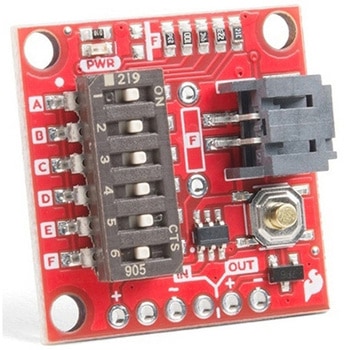
SparkFun Nano Power Timer - TPL5110
SPARKFUN¥2,398税込¥2,6381個33日以内出荷。Description。Sometimes we want our projects on, but sometimes we want to turn them off for a while to save power. The SparkFun Nano Power Timer will run while only consuming minimal power(approximately 35nA)and turn your project on after a set amount of time. When you are done polling your sensors, posting data to the web, writing to your logger, or planning world domination, your microcontroller can tell the Nano Power Timer to turn off the power. No more running your microcontroller all day when you only want to read the ambient temperature once per hour.。The TPL5110 delay is configured with the use of resistors. We've added a six-way DIP switch to select one of the five preinstalled resistors. The sixth switch is attached to a pad to add your own PTH(or SMD)resistor. The delays associated with the preinstalled headers are shown on the bottom of the board for quick setup. Additionally, you can select more than one switch to combine the resistors in parallel(up to 26 options not including the custom resistor), check out the hookup guide for a nice chart as to the total resistance and corresponding delay for each combination.。The Nano Power Timer can handle voltages between 1.8V and 5.5V as well as current up to 1.1A with times from 100ms to two hours(preconfigured settings range from 30s to 2h). You will find a button on the board which will allow you a quick override to the delay so you can turn your project on whenever you like.。Get Started with the SparkFun Nano Power Switch。Features。Supply Voltage:1.8V to 5.5V。Current consumption at 2.5V:35nA Typical(50nA Max)。Selectable Time intervals:100ms to 7200s(2 hours)。Timer Accuracy:1%アズワン品番67-0425-68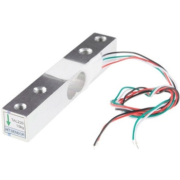
Load Cell - 10kg, Straight Bar TAL220
SPARKFUN¥3,998税込¥4,3981個33日以内出荷Description。This straight bar load cell(sometimes called a strain gauge)can translate up to 10kg of pressure(force)into an electrical signal. Each load cell is able to measure the electrical resistance that changes in response to, and proportional of, the strain(e.g. pressure or force)applied to the bar. With this gauge you will be able to tell just how heavy an object is, if an object's weight changes over time, or if you simply need to sense the presence of an object by measuring strain or load applied to a surface.。Each straight bar load cell is made from an aluminum-alloy and is capable of reading a capacity of 10kg. These load cells have four strain gauges that are hooked up in a wheatstone bridge formation. The color code on the wiring is as follows:red = E+, green = O+, black = E-, and white = O-. Additionally, these load cells offer an IP66 protection rating and feature two M4 and two M5 sized through-holes for mounting purposes.。Get Started with the Load Cell Guide。Features。80mm×12.7mm×12.7mm, 250mm Wireアズワン品番67-0426-52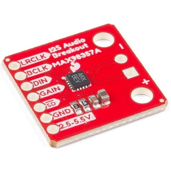
SparkFun I2S Audio Breakout - MAX98357A
SPARKFUN¥1,998税込¥2,1981個33日以内出荷Description。The SparkFun I2S Audio Breakout board uses the MAX98357A digital to analog converter(DAC), which converts I2S(not be confused with I2C)audio to an analog signal to drive speakers. The I2S Audio Breakout converts the digital audio signals using the I2S standard to an analog signal and amplifies the signal using a class D amplifier which can deliver up to 3.2W of power into a 4Ω load. The board can be configured to output only the left channel audio, right channel, or both.。The SparkFun I2S Audio Breakout board is fairly simple, requiring only a few pin connections to get it up and working. By default the board is configured in "mono" operation, meaning the left and right signals are combined together to drive a single speaker. If you want a separate speaker for the left and right audio channels you'll need to cut the mono jumper. In addition to being able to select the audio channel output, the gain can also be configured in a few ways. The gain of the amplifier can be configured from as low as +3dB to as high as +15dB. While the channel selection can be configured on board, the gain however is controlled externally using the gain pin. By default, the board is configured for +9dB, but can be easily changed!。Get Started with the SparkFun I2S Audio Breakout Guide。Features。Supply Voltage Range:2.5V - 5.5V.。Output Power:3.2W into 4Ω at 5V.。Output Channel Selection:Left, Right, or Left/2 + Right/2(Default).。Sample Rate:8kHz - 96kHz.。Sample Resolution:16/32 bit.。Quiescent Current:2.4mA.。Filterless Class D Outputs。No MCLK Required。Click and Pop Reduction。Short-Circuit and Thermal Protection.アズワン品番67-0422-64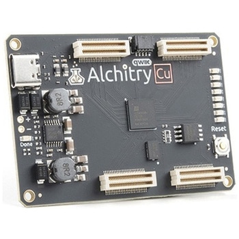
Alchitry Cu FPGA Development Board Lattice iCE40 HX
SPARKFUN¥15,980税込¥17,5781個33日以内出荷Description。If you are not needing a lot of power to start your FPGA adventure, or are looking for a more economical option, the Alchitry Cu FPGA Development Board might be the perfect option for you! The Alchitry Cu is a "lighter" FPGA version than the Alchitry Au but still offers something completely unique. FPGAs, or Field-Programmable Gate Arrays, are an advanced development board type for engineers and hobbyists alike to experience the next step in programming with electronics. The Cu truly exemplifies the trend of more affordable and increasingly powerful FPGA boards arriving each year. This board is a fantastic starting point into the world of FPGAs and the heart of your next project. Finally, now that this board is built by SparkFun, we added a Qwiic connector for easy I2C integration!。The Alchitry Cu uses the Lattice iCE40 HX FPGA with 7680 logic cells and is supported by the open source tool chain Project IceStorm. The Cu possesses 79 IO pins with eight general purpose LEDs; a 100MHz on-board clock that can be manipulated internally by the FPGA; a USB-C connector to configure and power the board; and a USB to serial interface for data transfer.。By adding stackable expansion boards similar to shields or HATs called "Elements," the Alchitry Cu is able to expand its own hardware capabilities by adding prototyping spaces, buttons, LEDs, and more!。The SparkFun Qwiic Connect System is an ecosystem of I2C sensors, actuators, shields and cables that make prototyping faster and less prone to error. All Qwiic-enabled boards use a common 1mm pitch, 4-pin JST connector. This reduces the amount of required PCB space, and polarized connections mean you can't hook it up wrong.。Get Started with our Learning FPGA Tutorials。Features。Lattice iCE40-HX8K FPGA - 7680 logic elements。79 IO pins(3.3V logic level)。USB-C to configure and power the board。Eight general purpose LEDs。One button(typically used as a reset)。100MHz on-board clock(can be multiplied internally by the FPGA)。Powered with 5V through USB-C port, 0.1" holes, or headers。USB to serial interface for data transfer(up to 12Mbaud)。Qwiic Connector。Dimensions of 65mm×45mm。。Examples。First FPGA Project - Getting Fancy with PWM。External IO and Metastabilityアズワン品番67-0423-08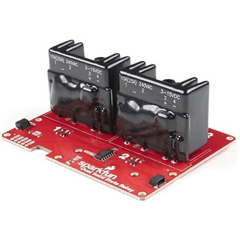
SparkFun Qwiic Dual Solid State Relay
SPARKFUN¥39,980税込¥43,9781個33日以内出荷Description。The SparkFun Qwiic Dual Solid State Relay is a power delivery board that allows users to switch two AC loads from a low power microcontroller using the SparkFun Qwiic connect system. The board features two 25A/250VAC solid state relays that utilize the Zero Cross Trigger method so you can toggle two loads on a 60Hz AC carrier signal on and off up to 120 times per second!。An ATTiny84 acts as the "brain" of the SparkFun Qwiic Dual Solid Relay to accept I2C commands to toggle the two relays as well as a few other special commands. The I2C address of the ATtiny84A is software configurable so, if you have a seriously big power project in mind, you could daisy chain over 100 Qwiic Dual Solid State Relays.。Messing with such high voltage is dangerous! We've included many safety precautions onto the PCB including ground isolation between the relay and other circuitry and a milled out area isolating each side of AC. However, with all the safety precautions included with the SparkFun Qwiic Dual Solid State Relay, this is still a power accessory for users who are experienced around, and knowledgeable about high AC voltage. If you're not comfortable with handling AC voltage in this way, you may want to check out the IoT Power Relay instead.。Note:The relays are rated for a max of 25A with forced air cooling. If you do not have forced air cooling, 10A max through the relays is recommended.。The SparkFun Qwiic connect system is an ecosystem of I2C sensors, actuators, shields and cables that make prototyping faster and less prone to error. All Qwiic-enabled boards use a common 1mm pitch, 4-pin JST connector. This reduces the amount of required PCB space, and polarized connections mean you can't hook it up wrong.。Get Started with the SparkFun Qwiic Dual Solid State Relay Guide。Features。Operating Voltage:2.5-3.6V(3.3V recommended)。I2C Address:0x0A(Default)0x0B(Alternate via jumper select)。Load Voltage Range:12-280VAC。Max Current(Through Relay):25A(240VAC with forced air cooling)。Zero Cross Trigger。Normally Open Circuit Only。2x Qwiic Connectorアズワン品番67-0421-58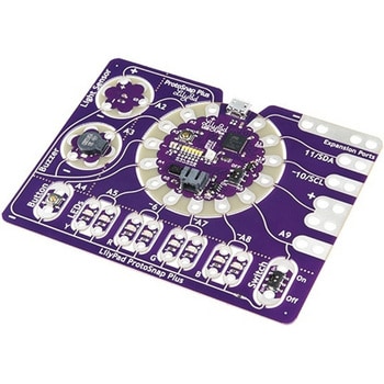
LilyPad ProtoSnap Plus
SPARKFUN¥14,980税込¥16,4781個33日以内出荷Description。The LilyPad ProtoSnap Plus is a sewable electronics prototyping board that you can use to explore circuits and programming, then break apart to make an interactive fabric or wearable project. Programming the ProtoSnap Plus is easy with the free Arduino software you'll need to program the ATmega32U4 on LilyPad USB Plus at the heart of the board. Once you've installed the software, you'll be able to write and upload your own programs to the board, making it do almost anything you want.。At the center of the ProtoSnap Plus is the LilyPad USB Plus microcontroller, pre-wired to a LilyPad board including a LilyPad Light Sensor, LilyPad Buzzer, LilyPad Button Board, four pairs of colored LilyPad LEDs and a LilyPad Slide Switch. Because these components are connected together on the ProtoSnap board, you can test out your project ideas before you sew. The ProtoSnap Plus also includes expansion ports that let you sew your wearables together or use alligator cables to easily connect external sensors and components. After testing out your coding ideas using the attached LilyPad pieces, you can break apart the prototyping board and sew them into your project!。Please be aware that the Lilypad ProtoSnap Plus is。NOT supported on Windows 7/8。due to a lack of support drivers for those specific OS's.。Note:。A portion of this sale is given back to Dr. Leah Buechley for continued development and education in e-textiles.。Get Started with the LilyPad ProtoSnap Plus Guideアズワン品番67-0422-45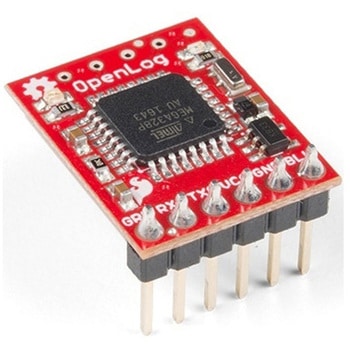
SparkFun OpenLog with Headers
SPARKFUN¥6,898税込¥7,5881個33日以内出荷Description。The SparkFun OpenLog with Headers is an open source data logger that works over a simple serial connection and supports microSD cards up to 64GB. The OpenLog can store or "log" huge amounts of serial data and act as a black box of sorts to store all the serial data that your project generates, for scientific or debugging purposes. This version of th OpenLog even includes pre-soldered headers for your convenience.。The SparkFun OpenLog uses an ATmega328 running at 16MHz thanks to the onboard resonator. The OpenLog draws approximately 2-3mA in idle(nothing to record)mode. During a full record OpenLog can draw 10 to 20mA depending on the microSD card being used.。All data logged by the OpenLog is stored on the microSD card. Any 512MB to 32GB microSD card should work. OpenLog supports both FAT16 and FAT32 SD formats.。For even better performance the OpenLog Artemis is the tool you need, featuring logging speeds up to 500000bps.。Get Started with the SparkFun OpenLog Guide。Features。VCC Input:3.3V-12V(Recommended 3.3V-5V)。Log to low-cost microSD FAT16/32 cards up to 32GB。Simple command interface。Configurable baud rates(up to 115200bps)。Preprogrammed ATmega328 and bootloader。Four SPI pogo pins。Two LEDs indicate writing status。2mA idle, 6mA at maximum recording rate。Pre-soldered Headersアズワン品番67-0422-30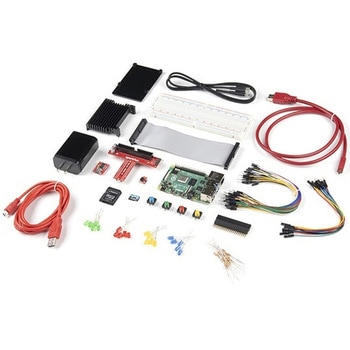
SparkFun Raspberry Pi 4 Hardware Starter Kit - 4GB
SPARKFUN¥56,980税込¥62,6781個33日以内出荷Description。The Raspberry Pi 4 Hardware Starter Kit provides a solid set of parts and instruction for working with the Raspberry Pi 4 in a more hardware-centric manner. While the Raspberry Pi isn't typically considered a go-to for hardware projects, its I/O pins hold a lot of benefits that you can use for a variety of applications. This kit covers the basics like using LEDs, and Buttons while providing a solid set of parts for working with any other hardware I/O and the 40-pin header. In addition, we've included all the parts needed for getting the Raspberry Pi 4 up and running whether it's on its own, or using a monitor(not included). The new 64GB MicroSD cards keep read/write commands running super fast, too.。Most of the contents of the kit rely on the use of the 2x20, 40-pin header, so we've included a special extender to allow you to plug in the ribbon cable while using the provided heatsink case. We've also included a Qwiic Shim for easily working with I2C based Qwiic boards with the Pi. No soldering is required for this kit!。Note:This variation includes the 4GB RAM option for the Raspberry Pi 4.。Get Started with the Raspberry Pi 4 Model B Guideアズワン品番67-0424-46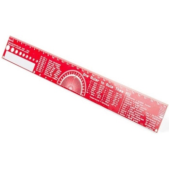
SparkFun PCB Ruler - 12 Inch
SPARKFUN¥3,198税込¥3,5181個33日以内出荷Description。One ruler to rule them all. This is a basic 12 inch ruler, but made from a PCB. We have included a lots of useful information on each side of the ruler that you might use on a daily basis including Wire Gauge holes, transistor diagrams, common fractions, Roman numerals, and metric to imperial conversions. Most importantly, the ruler provides you with a straight line and centimeter markings one side and inch markings on the other side.。You'll also find a small protractor in the middle for all your angle measurement needs. While we figured you have a fairly good idea how to use a ruler we do have a tutorial to explain all the information you'll see!。Get Started with the How to use a Ruler Guide。Features。12 inch PCB ruler with markings down to 0.05" or 1/32"。30.48 cm PCB ruler with markings down to 0.1mm。Electrical Equations such as Ohm's Law and Parallel Resistors。Keyboard Alt Codes。Color Wavelengths。Protractor。Metric Prefix Summary Chart。Metric conversions。Morse Code。Transistor Diagrams。Roman Numerals。Fraction Summary。Wire Guage Chart。Tap and Drill Chart。Size:12"x 1.5"アズワン品番67-0428-67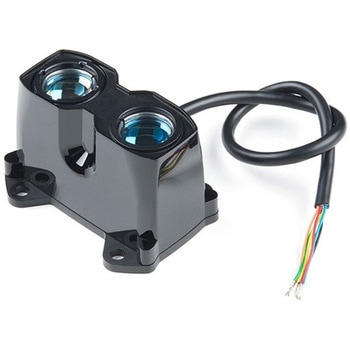
LIDAR-Lite v3HP
SPARKFUN¥49,980税込¥54,9781個33日以内出荷Description。LIDAR has never looked so good! This is the LIDAR-Lite v3HP, a compact, high-performance optical distance measurement sensor from Garmin(TM). The LIDAR-Lite v3HP is。the。ideal optical ranging solution for drone, robot, or unmanned vehicle applications. Each sensor is housed in a durable, IPX7-rated housing and includes all the core features and user configurability of the popular LIDAR-Lite v3.。The v3HP is very similar in function to that of the v3 but it can now sample faster at rates greater than 1kHz(where as the v3 is only capable of up to 500Hz). Another improvement is that this v3HP model is more power efficient with current consumption rates 40mA less than the v3(that's 65mA as opposed to 105mA while idle, and 85mA instead of 130mA while acquiring).。Each LIDAR-Lite v3HP has a range of 1m to 40m and features an edge-emitting, 905nm(1.3 watts), single-stripe laser transmitter, 8m Radian beam divergence, and an optical aperture of 12.5mm. This version of the LIDAR-Lite still operates at 5VDC(6V max)with a peak power of 1.3W and still possesses an accuracy of +/- 2.5cm at >2m. On top of everything else, the LIDAR-Lite is user-configurable, allowing adjustment between accuracy, operating range and measurement time and can be interfaced via I2C or PWM with the attached 200mm cable.。Note:CLASS 1 LASER PRODUCT CLASSIFIED EN/IEC 60825-1 2014. This product is in conformity with performance standards for laser products under 21 CFR 1040, except with respect to those characteristics authorized by Variance Number FDA-2016-V-2943 effective September 27, 2016.。Get Started with the LIDAR-Lite v3HP Guide。Features。Resolution:1 cm。Typical accuracy:+/- 2.5cm at distances greater than 2 meters(Refer to operating manual for complete operating specifications)。Range:1m to 40m。Update rate:Greater than 1kHz。Interface:I2C or PWM。Power(operating voltage):4.75-5VDC; 6V Max。Current consumption:65ma idle; 85ma during acquisition。Operating temperature:-20℃ to 60℃。Laser wave length/Peak power:905nm/1.3W。Beam divergence:8m Radian。Optical aperture:12.5mm。Water rating:IPX7。Unit dimensions:24.5mm×53.5mm×33.5mm(1.0in×2.1in×1.3in)。Weight:34g(1.2oz)アズワン品番67-0426-76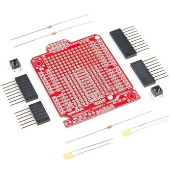
SparkFun ProtoShield Kit
SPARKFUN¥4,998税込¥5,4981個33日以内出荷Description。The SparkFun ProtoShield Kit lets you customize your own Arduino shield using whatever circuit you can come up with and then test it to make sure everything is working the way it should! The SparkFun ProtoShield Kit is based off the Arduino R3's footprint that allows you to easily incorporate it with favorite Arduino-based device.。One of our favorite features with this version of the ProtoShield Kit is the solderable-like breadboard prototyping area! Half of this area was designed with a breadboard in mind. On the underside of the shield you will be able to see open jumper pads between each through hole to make a connection like a breadboard. Once you add a component, simply add a solder jumper between holes to make a connection. For those that prefer the standard prototyping pads, we left the other side(near the BlueSMiRF and Serial UART ports)as is.。We have also moved the prototype testing components(those used to make sure your circuit works effectively)off of the "mainland" of the shield and onto a ProtoSnap styled, removable PCB. On this test area you will find soldering areas for the two yellow 3mm LEDs(as well as pins to control and power them), two 330 Ohm resistors, a 10K Ohm resistor, and a pushbutton.。Note:。Since this product is a kit, assembly and a basic knowledge of soldering will be required. The SparkFun ProtoShield Kit does not come pre-assembled.。Get Started With the SparkFun ProtoShield Kit Guide。Features。Arduino R3 Footprint。Soldering Kit。Solderable-Like Breadboard。BlueSMiRF or Comparable 6-pin Pins。Detachable Test Areaアズワン品番67-0422-25


『オフィスサプライ』には他にこんなカテゴリがあります